2

I am designing a PIR sensor circuit to detect human movement. I am supposed to display movement using an oscilloscope (the response from this PIR sensor.)

I have used the following circuit but it does not show any response on the oscilloscope.

Is there anything that I need to add?

enter image description here

JRE
  • 71,321
  • 10
  • 107
  • 188
user355274
  • 23
  • 4
  • Please post specifications/datasheet for the PIR Sensor, there are many types. – Mattman944 Nov 15 '23 at 13:34
  • It is PIR sensor MURATA IRA-S210ST01 – user355274 Nov 15 '23 at 13:49
  • The common mode input range of the 741 doesn't go down to the negative rail. Trash this design and use at a minimum an LM324. One section to amplify, another to compare. – Mattman944 Nov 15 '23 at 14:09
  • With your scope on pin 2 and ground on pin 3 of the PIR. Set the scope to a sensitive setting. Wave something really hot in front, like a soldering iron. – Mattman944 Nov 15 '23 at 14:11
  • @Mattman944 could you clarify a bit more for me , so I need a LM324 instead of 741 and should I keep the transistor as a first stage amp or not – user355274 Nov 15 '23 at 14:18
  • 1
    Mandatory read on 741: https://electronics.stackexchange.com/questions/304521/reasons-not-to-use-a-741-op-amp – winny Nov 15 '23 at 14:27
  • I would not use a transistor. For low-power, <100 kHz, an opamp is almost always a better choice. Note that an LM124, LM224, LM324 are the same, first digit is the temperature range. 1 = Military, 2 = Industrial, 3= Commercial. – Mattman944 Nov 15 '23 at 16:37

1 Answers1

3

As in the comments the 741 op-amp is not one of the better choices.
Consider using one of the test circuit configurations in the IRA-S210ST01 datasheet, these also use an op-amp similar to that recommended in the comments.

For additional info you can refer to this application sheet. The document also includes a prototype starter board that should be available, schematic included.

In your original circuit you are using the transistor as a switch rather than a linear amplifier. If you want to view an amplified analog output try using one of the the circuits in the datasheet or application sheet to start.

Since the LM224 op-amp (and similar versions) have multiple parts in one package you can implement an analog stage, a filtering stage, and a comparator stage. Below is one of the test circuits from the datasheet.

Test circuit

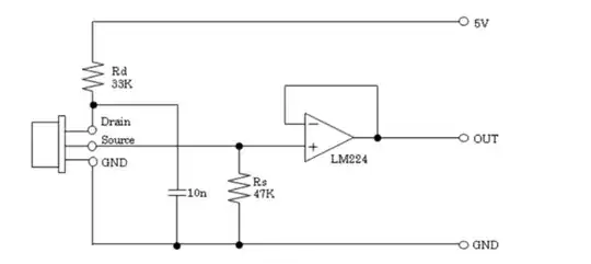
(From Murata datasheet Fig. 5)
.

Nedd
  • 10,391
  • 17
  • 24
  • Thank you it is working perfectly but is there anyway to reduce the SNR – user355274 Nov 16 '23 at 11:48
  • What is the pictured test circuit supposed to do? – cornelius Jan 13 '24 at 10:51
  • @cornelius - The circuit above only outputs a buffered analog signal from the sensor. The signal can be further amplified, filtered, and sent to a comparator if needed. For more info see the original question above and the Murata datasheet link just below the circuit. – Nedd Jan 14 '24 at 23:41