0

I have to design an industrial system that is comprised of several modules. The system consists of one "master" and several "slaves". As the roles imply, the master will coordinate communications and poll the slaves.

Let me show you the way these master and slaves have to be connected before going any further since that is key to understanding my questions.

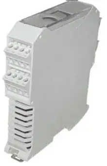
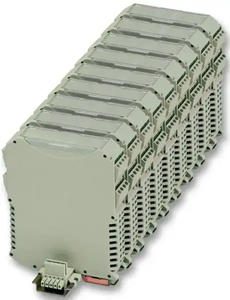
Both master and slave modules will be DIN-rail mounted and will be created using these electronic enclosures:

DIN Rail Enclosure

These enclosures work on a TBUS system and mount on the DIN rail over connectors like these: DIN Rail Connector
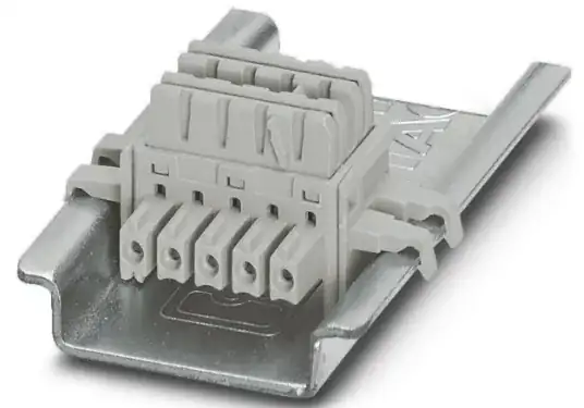
So it will look something like this:

TBUS System

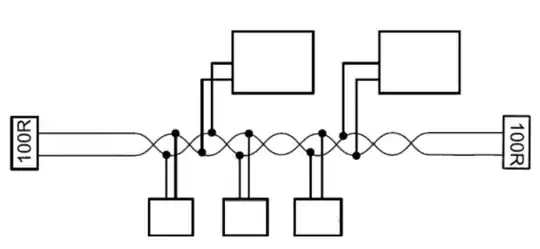
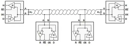
So, what I'm having problems with my design is how to reliably and robustly create the communications between these modules. At first, I thought about RS485 or CAN but I think both would be overkill. I'm not sure if they would work in such a bus since the connection between modules is very short, there are no twisted pair cables communicating each module over long distances so I'm not sure RS485 or CAN make sense electrically or if they would work because I don't have something like this:

CAN/RS845 Bus

Or this:

CAN/RS485 Bus Alt

I think the best way to do this is just regular SPI or I2C but now my doubt is about noise immunity. SPI and I2C are for inter-chip communications on the same board and doing something like this would stretch that concept. Since this system will be in a very electrically noisy environment I fear that a simple SPI or I1C bus like the one you would have on a board would not work.

My question then is: What can I implement to reliably communicate my modules in an electrically noisy environment on a bus system like this?

In software, I can implement all sorts of error correction and packet verifications to compensate for the noise or possible data loss, but I still would like the electrical part to be as stable as it can be because the system needs fast and constant communication between the master and the slaves. By fast I'm not saying like GBPS or anything like that, but I would like to go faster than a couple KBPS.
JYelton
  • 34,119
  • 33
  • 145
  • 265
m4l490n
  • 345
  • 3
  • 11
  • 4
    I don't know man buses that are simpler than RS485. Can you put into words why you would say it's overkill? – Marcus Müller Nov 11 '23 at 18:04
  • 2
    I think that in this case, having a run that is so short that there is no cabling is better than a longer run that uses it. I second RS485 for its simplicity and common-mode rejection. – vir Nov 11 '23 at 18:12
  • m4l490n - Hi, In order to comply with the Stack Exchange rule for referencing, please [edit] the question & add a link to the webpage / PDF / video etc. which was the original source for each image (and please remember it's your responsibility to do that in future). Thanks. – SamGibson Nov 11 '23 at 18:13
  • 1
    I also support RS485 for this application. And since the "cable length" is so short you probably don't even need termination. – brhans Nov 11 '23 at 19:02
  • 1
    A cable so short that you don't need cable is a good, rather than bad, thing. Use 485, it's not overkill, especially as you say it's a noisy environment. It's built for your purpose, why make life difficult for yourself? – Neil_UK Nov 11 '23 at 19:36

1 Answers1

0

For a project i created a similar system once.

We had the same basic requirements and took the following approach:

(1) Bus Interface:

We selected RS485 as cheap driver ICs are available, they usually come fail-safe and are more than reliable for these short "cable-runs". A bonus was, that we were able to connect different "module stacks" by simply using a wire. For addressing we used the common 2pc 4bit HEX rotary switch interface.

(2) Bus Controller:

We decided to "outsource" the entire bus interface for a seperate controller. This controller was interfaced to the main module controller via SPI. To the module mcu, we used a simple range base R/W interface (Read/Write x byte starting from 0x...).

The bus interface was more complicated: Token-ring time-multiplex (You don't need it i guess), message based, bootloader stuff, etc....

I recommend this approach, as you could re-use the interface controller as ready-to-solder component. You do not need to integrate the "dedicated application software" with the "comm interface" again and again....

(3) Power supply:

We just feed the +24V supply through the rack-bus along the RS485 and a dedicated 5V rail. This 5V rail was generated by a dedicated "Power-Supply-Module" on the stack. We used this approach, as the whole ESD/EMI protection etc. for the 24V input could be put into this module and every other module requires some logic rail. By providing this 5V, we could use a simple and cheap 3V3 LDO instead of a 24V/3V3 DC/DC.

You can add voltage/current/Power monitoring/logging in the PSup-Module via the Bus-Interface

(4) Bus protocoll:

As we had no requirement to integrate with thrid-party devices, we could roll our own protocoll. As i said, we had a multi-master application, so a little bit more complex than Master/Slave.

You have to judge for your own - based on your requirements - if to roll your own or go with something "standard" on GitHub.

(5) Summary:

  • Dedicated PSup-Module to simplifie power architecture of overall system
  • RS485 as physical layer suited, as cheap ICs/reliable/ESD-Safe/Miswiring-Safe
  • Spend time thinking about your protocoll requirements but don't overdo it
  • Maybe dedicated bus-controller MCU/FPGA
ElectronicsStudent
  • 3,489
  • 7
  • 20