6

I have an analogue oscilloscope that had its power cable head chewed off by something. Before I replace the cable, I want to be 100% sure which side of the cable is hot and which is neutral. This is for North America and the cable has no ground.

My understanding is that for North America, when facing an outlet the right side is hot leaving left as neutral. I'm assuming that devices would have their wires oriented that way, but I don't want to rely on that assumption.

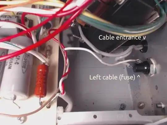
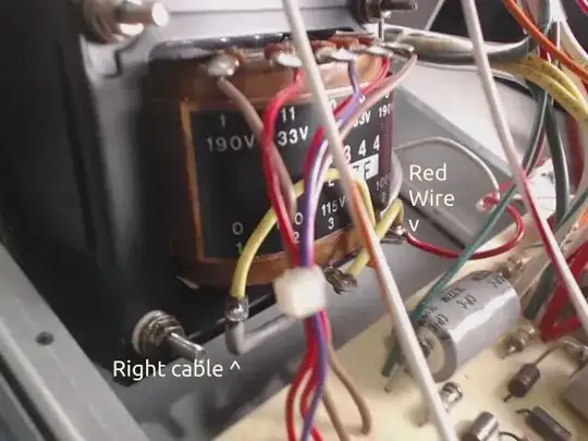
One wire goes directly into a fuse, and the other into what I'm assuming is a rectifier. Both of those cables lead to the power switch, with the fuse line being white and the rectifier being red. Do the cable colors indicate which is hot?

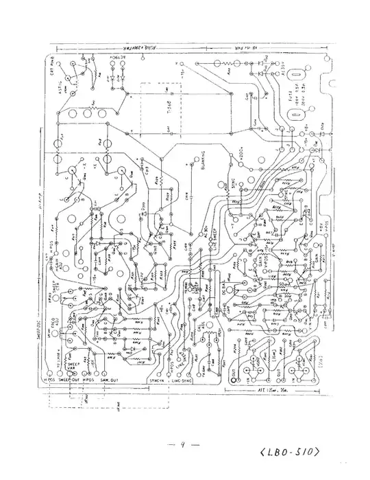
There is a service manual online with a schematic, but I do not have the skills to read it. The manual is also for a different model, this is for the LBO-510A, and the schematic is for the LBO-510. I will discharge the CRT.

What can be taken from this information? In this case, what could happen if I get it wrong? Before I try anything I want to understand what risks could be involved, or other things a complete amateur would overlook.
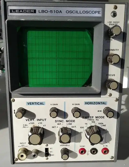
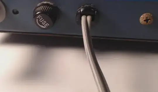
Leader LBO-510A Oscilloscope

Cable entering device

Internal side of cable

Right side + red wire

Service manual (page 10 of pdf in link): https://www.download-service-manuals.com/en/model.php?id=5514

Service manual (page 10 of pdf in link)

JRE
  • 71,321
  • 10
  • 107
  • 188
zuzomuzabi
  • 81
  • 7
  • 3
    I guess we are talking AC here? AC is for ALTERNATING current. There is no left or right. You can swap your cables to the Transformer however you want and have the same result. – S_G Nov 02 '23 at 09:16
  • This on marked page 16 is the schematic part that matters to your question. So far as I can tell from this, the transformer core is grounded but there's no indication that either of the T or S leads coming from mains power are chassis-grounded anywhere. Perhaps someone else can spot it. But I don't see it. – periblepsis Nov 02 '23 at 10:02
  • 3
    North-American NEMA outlets do not have a standard orientation, so describing the pins as left or right is not going to give you clearly defined hot/neutral connections. – brhans Nov 02 '23 at 12:02
  • 1
    Are you doing this for retro/nostalgia purposes or because you actually plan to use it? I mean... has it been calibrated since the 1980s? :) – Lundin Nov 02 '23 at 15:29
  • @S_G / brhans My understanding of all things AC is simple, thank you for clarifying. – zuzomuzabi Nov 03 '23 at 09:14
  • @periblepsis Not sure if it would be different for the 510A, but I think page 16 is covering the 310, 310A and 311. You're saying that what I thought was a rectifier is a transformer, and some extra searching proved you right. Is there a rectifier at all? I wouldn't think the oscilloscope could run on AC, but what do I know. – zuzomuzabi Nov 03 '23 at 09:14
  • @Lundin $10 at a flea market, I just couldn't say no. It's not for anything close to serious, I would be thrilled if I could get it to do much of anything :) – zuzomuzabi Nov 03 '23 at 09:15
  • @zuzomuzabi Yes, there are rectifiers. And they show up in the snip of the schematic I pointed out, quite close to the transformer there. – periblepsis Nov 03 '23 at 09:23

1 Answers1

20

Which wire is hot doesn't matter. According to the schematics in the service manual, both wires from the power plug go straight into the transformer (via the fuse and switch.) If hot/neutral mattered, one of them would be connected to the chassis of the oscilloscope. Neither is connected to the chassis.

This is borne out by your photos showing a two lead AC power cord connected directly to the transformer.


I personally would not want to use this scope. The grounds of the input leads (BNC connectors for the probes) are connected to chassis ground, but the chassis is floating.

This means that you can connect the leads to, say, a 120V outlet and it won't go "Bang!" It also means that when you do that, the whole chassis (all touchable metal surfaces) will be at 120VAC.

You might as well put a sticker on it that says "kill me now."

Read here to see why a floating chassis is a really bad thing.

Your scope is floating by design. That is scary.


I would replace the two conductor power lead with a three conductor lead with a grounded plug. Connect the live and neutral any way you like to the transformer, then connect the ground wire (green+yellow) to the chassis of the oscilloscope. Always use a properly grounded outlet for power.

With it connected that way (like any reasonable scope,) you can no longer clip the ground wire to high voltage to make floating measurements - but you will also no longer be able to kill yourself.


On polarized outlets (NEMA 1,) what they have is a wide pin and a narrow pin. The wide pin is neutral. See also NEMA 5. Not all NEMA 5 outlets have a narrow and a wide slot.

Put a grounded power cable on that scope and save yourself some headaches and dangers.

JRE
  • 71,321
  • 10
  • 107
  • 188
  • 12
    I wouldn't say "which wire is hot doesn't matter". It doesn't in normal operation. But when the fuse blows, it is preferable to separate the hot wire from the oscilloscope rather than neutral. So if the plug has a preferred direction (essentially mainly when they are angled in which case the cord will likely be more often plugged in angling down), there is some preference for having the hot wire go to the fuse. That will somewhat reduce the amount of accidents expected to happen, even though as you note, it is by no means "safe". – user107063 Nov 02 '23 at 14:56
  • 7
    I would also use a DMM to check the resistance from each of the AC input wires to the chassis, just to make sure there isn't already a 'sneak' path in the scope circuit from the mains side to the chassis, or that someone else didn't already modify the circuit to connect the chassis to the mains side. – LevelUpEELab Nov 02 '23 at 15:35
  • @JRE Thank you for taking the time to reply with such depth - it is greatly appreciated. I would have otherwise never read anything about floating chassis, or the dangers that come with that.

    I will take your advice and use a cable with ground. Page 4 of the user manual lists a "ground socket" that connects directly to the chassis. I will connect the green wire of the NEMA 5 cable to the inside nub of that socket.

    Just to check my understanding, if I did connect to a 120V outlet, the chassis would be hot for a split second, and then power would be cut by a breaker. Is this correct?

    – zuzomuzabi Nov 03 '23 at 09:10
  • @user107063 Makes sense, good to know. I'll connect the hot wire to the fuse for what that's worth. – zuzomuzabi Nov 03 '23 at 09:12
  • @LevelUpEELab Everything seems to be in order, not getting a reading for either of the cables when touching the chassis. – zuzomuzabi Nov 03 '23 at 09:12
  • 1
    @zuzomuzabi: As it is now, if you connect the probes to 120VAC then the whole housing would be at 120VAC. The circuit breaker would not trip. It would sit there quietly waiting for you to touch it and get zapped. When you add the ground wire, the breaker would trip as soon as you connect the ground wire of the probe to the 120VAC. – JRE Nov 03 '23 at 09:36