1

I am building an integrator circuit on a breadboard using an LM741 op-amp. Below is the circuit diagram: enter image description here

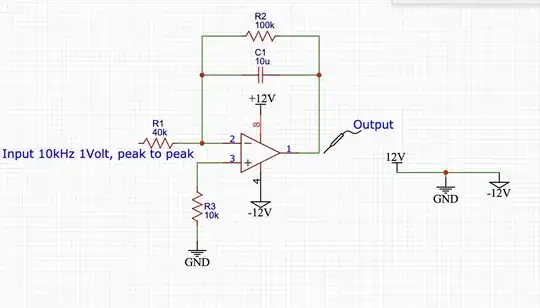
The input to the circuit is a 10 kHz signal with a peak to peak of 1 volt (with 0 offset). The circuit integrates the signal (input: sine wave, output: cos wave ...... input: square wave, output: triangle wave, ect) I am using an oscilloscope to look at and measure the output. I have the power supply connected in series so the op amp has +12, and -12 V, with the non inverting input connected to 0 V.


The problem is, the output wave is offset by a voltage of around 6 V(it varies if I adjust the voltage on the power supply). The peak to peak is as expected on the output. But I can not figure out how to get rid of the output offset?

winny
  • 14,707
  • 6
  • 46
  • 66
MattODwyer
  • 27
  • 3
  • 1
    In maths, any integration generates a $+c$ constant, that's the offset you see :) Apart from the joke, it might depend on the start phase. – Rohat Kılıç Oct 27 '23 at 12:15
  • 1
    Your power supply network on the right of the schematics looks quite absurd. What lines (and labels) do you use on your board, what lines on your power supply? – user107063 Oct 27 '23 at 12:17
  • @RohatKılıç R2 stops this from being an integrator. Start phase DC offset is removed; the RC feedback network has a time constant of 1s, corresponding to a 0.15Hz lowcut. – user107063 Oct 27 '23 at 12:24
  • 2
    Mandatory read on 741 usage: https://electronics.stackexchange.com/questions/304521/reasons-not-to-use-a-741-op-amp – winny Oct 27 '23 at 12:36
  • @winny Max bias current 1.5µA. On 40k|100k, this is probably good for 50mV. Which is bad but nowhere near 6V. DC amplification is 2.5. Still nowhere near 6V. – user107063 Oct 27 '23 at 12:51
  • 1
    Please provide oscillograms of IN+, IN- and OUT pins with reference to your ground. Do you have any decoupling on the power supply pins? – winny Oct 27 '23 at 13:28
  • 3
    Why have you shorted out all your power supplies on the right? – Hearth Oct 27 '23 at 13:54

2 Answers2

4

I am building an integrator circuit on a breadboard using an LM741 op-amp.

This is the pin allocation for a 741 slop-amp: -

enter image description here

  • You have assumed your output is on pin 1 and this is wrong.

  • You have also assumed the power pin is pin 8 and this is also wrong

enter image description here

  • I won't bother mentioning the other things folk have said.
Andy aka
  • 456,226
  • 28
  • 367
  • 807
1

For the output to be centred on 0 V the input waveform must have a negative going excursion exactly the same as its positive going excursion. There will be an output offset if the input's positive going excursion is different in amplitude or different in time to its negative going excursion.

  • 1
    6V is half the power supply voltage. This is more likely to be a misunderstanding about how to supply ±12V. – user107063 Oct 27 '23 at 12:21
  • @user107063 Half the supply voltage would be 12V if it's actually a bipolar supply as shown. They may have a total of 12V and are calling it ±12V when it's actually ±6V though. – GodJihyo Oct 27 '23 at 14:30