3

Can I please get some inputs as to what is missing or incorrect in my schematic? I am building a controller box with an Arduino to control a car's beams and wiper motor speeds.

Schematic

I will do a quick walk through. I will control the headlights with a LDR and solar cell. I don't have the rain sensor yet as I am looking at building this with a a sensor that will push light and a sensor that will receive the light.

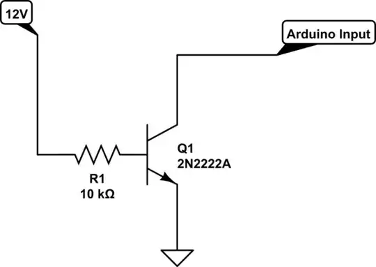
I have a full time power connection to the Arduino with a DC/DC converter and then 4 switches that will control the ignition, beam auto on, wiper auto on and beam auto cancel override. For these switches I want to use 2N2222A transistors with 12V incoming on the base and earth through the collector and emitter. Between these power and transistors I have a 10k resistor, then I use same transistors on the LDR and solar cell as I don't want these to permanently send data only when the ignition is on, and there I have a 4.7k resistor. To control the beams and wipers I will use 4 relays and this will be controlled by my two output connections.

JRE
  • 71,321
  • 10
  • 107
  • 188
CJ Bester
  • 31
  • 2
  • You should think twice about these two applications, especially the wiper control. If there's a downpour and the wipers stop, it could lead to a dangerous situation for you and other road-users. – MiNiMe Oct 26 '23 at 10:39
  • Emitter and collector of Q1-Q4 are swapped – Jens Oct 26 '23 at 11:21
  • the two transistors on the right side are drawn upside down – jsotola Oct 26 '23 at 15:21
  • @MiNiMe, I don't see the problem, you still have fun control on your manual switches which will override auto. – CJ Bester Oct 30 '23 at 11:17
  • Just telling you, when it comes to automotive circuits everything electrical is at another level. If you look at components there are different models for automotive and regular use. – MiNiMe Oct 30 '23 at 11:26

2 Answers2

4

For a first circuit diagram, that's a great start.

  • Of course it takes practice and time to make good circuit diagrams. They don't just "happen", they are work.

  • The conventional placement and flow is important. There are lots of basic rules such as voltage falls like gravity -- so up is up! So your battery and your CPU need rotating.

  • We always are asking where is ground, where is power (of various kinds), what is input and what is output. You can fix these on your diagram easily.

  • Always blob connections, Don't use diagonals.

  • Don't draw wires for power and ground, use symbols

Read about good practice https://electronics.stackexchange.com/a/28255/173919

Of course there are exceptions to most rules, but for a simple diagram like yours there's no reason to not follow them.

jonathanjo
  • 14,034
  • 3
  • 34
  • 66
1

This is pretty much backwards to the normal way of doing things: enter image description here

You have things setup to pull the Arduino input high when you turn on the switch. Most folks use a pull up resistor on the Arduino input then arrange the external circuit to pull the Arduino input to ground.

You can use the circuit the way you have it, but you'll have to put a pulldown resistor in the circuit then use pinMode "INPUT" instead of pinMode "INPUT_PULLUP."

enter image description here

Normally, you'd do it this way:

schematic

simulate this circuit – Schematic created using CircuitLab

You set the pinMode to "INPUT_PULLUP." When the external switch is on (12V to the base resistor of the transistor) the Arduino see a low on its input.

JRE
  • 71,321
  • 10
  • 107
  • 188