I'm trying to test a mechanical rotary encoder for a piece of industrial equipment. I'll attach pictures, but basically the encoder operates by monitoring a slowly rotating perforated wheel. The perforations either open or obscure the line of sight between an infrared LED and a phototransistor. There are two sensors and I assume that the two sensors placed in close proximity are used to detect the direction of motion.
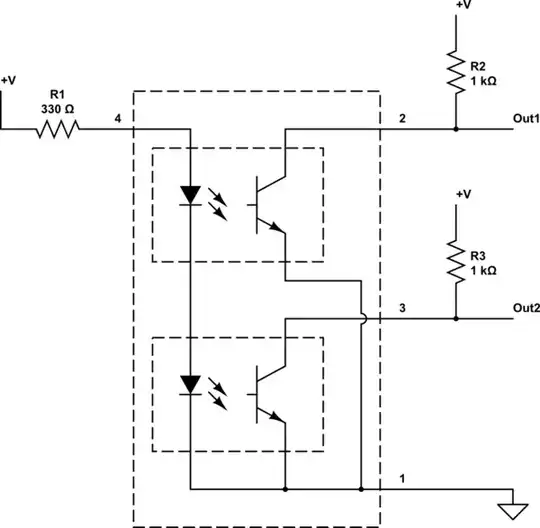
The two sensors are Vishay TXST2300 (https://www.vishay.com/docs/81147/tcst2103.pdf) and are wired as per the attached diagram which I drew by using a Fluke meter in continuity mode and literally diagraming the tracings on the board as best I can. The problem is that the resulting circuit doesn't make sense to me so I either have: (a) incorrectly diagrammed the circuit, or (b) don't understand how the sensors are supposed to work.
I was expecting: (a) power (+5V DC) to all four "+" pins, (b) ground connected to the two "E" pins in order to keep the infrared LED's lit, and (c) separate signal lines to each of the "D" pins on the phototransistors. Based on this expectation the 4-pin connector would have: (1) power, (2) ground, (3) signal a, and (4) signal b pins.
Instead, the "+" pin from each phototransistor goes to a dedicated pin on the 4-pin connector. This would suggest 3 power pins and 1 ground on the 4-pin connector.
Again, I either (a) diagramed this incorrectly, or (b) don't understand how this is supposed to work, or (c) something I'm missing.
Any feedback would be greatly appreciated - is my confusion related to a, b, or c?
Ironically, I purchased a couple TCST2300 sensors, wired one onto a breadboard along with an Arduino Uno (Rev 3) according to the TCST2300 test diagram in the data sheet and it worked perfectly which is why the wiring on the little PC board is so confusing. I'll also attach pictures of the test circuit diagram from the data sheet and a screenshot of the output on a DS212 pocket oscilloscope - again, this test circuit appeared to work as I expected, but didn't add any insight into the circuit on the PC board I'm trying to test.
My goal is to: (a) identify the power and ground pin on the 4-pin connector so I can verify that the little PC board with the TSCT2300s is actually getting power from the mother board, and (b) ultimately design a test circuit so I can test the little PC board with the Arduino.
Thanks in advance - this one has got me stumped!
PS: I'm a self-trained hobbyist which probably explains some of my confusion!


