The "voltage" of a cell or battery is only a measure of the potential difference between its two terminals. That is, a 9V battery's positive terminal is known to be 9V more positive (9V higher in potential) than its negative terminal. Those 9V tell you nothing about the the absolute potential of either terminal.
Absolute potential doesn't exist, since there's no point in the universe that you could call "zero" volts, but nothing's stopping you from declaring an artificial "zero" (ground) at any point in your circuit, and quote all potentials elsewhere relative to that. This practice simplifies circuit analysis and descriptions. If you've declared that a 9V battery's negative terminal is "ground" (0V), then it's easier to say that "the positive terminal is +9V", than "the difference in potential between the positive and negative terminals is 9V, and the positive terminal potential is the higher of the two".
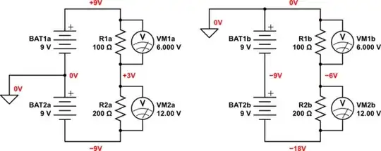
This means you could declare either terminal of the battery to be 0V (ground), and since this you do this only as a matter of arithmetic/descriptive convenience, it doesn't change potential differences anywhere, and therefore doesn't change the behaviour of the circuit at all:
simulate this circuit – Schematic created using CircuitLab
I've declared "ground", the zero-volt node, in different places in those two circuits, but the voltages across all elements remains the same, the current through all elements remains the same. Behaviour is the same in both cases.
For the purpose of analysis and communication with other engineers, I've marked the "absolute" potentials in red. They aren't really absolute, they're just quoted relative to to our designated zero point.
It also helps that the ground symbol can be used in many places around a schematic, indicating that all such nodes are physically joined, electrically connected together. Considering that this ground point will probably be used by many, many other parts of larger systems, this convention helps keep the schematic uncluttered.
Apart from that, the node we declare to be ground, having a potential of 0V, is completely arbitrary, and doesn't influence circuit behaviour.
Kirchhoff's Voltage Law (KVL) doesn't have a concept of absolute potential, it deals exclusively with potential differences across elements in a loop. This means it's safe to raise or lower all absolute potentials in a circuit by the same amount, without upsetting any KVL results. All KVL says is that whatever absolute potential you start with, at some node in a loop, all the potential increases and decreases that you encounter as you travel around that loop must bring you back to that same potential when you eventually get back to the starting node. In other words, potential change around the entire loop must always be zero, regardless of the absolute potentials at any individual node along that path.
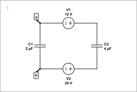
By the way, it seems to me that circuits (b), (c) and (d) in your pictured question don't have a single solution. In those circuits, there are infinitely many solutions to \$V_a - V_b\$. The capacitors can each have any potential difference, as long as KVL isn't violated, and where they settle will depend on their initial charge, battery internal resistance, and the order in which the circuit is assembled.


