Please help me something that I don't understand:
Why is there a need for pull-down resistors in the circuit below with push button if the ground has already zero voltage? This is the only thing I find confusing in them.

Please help me something that I don't understand:
Why is there a need for pull-down resistors in the circuit below with push button if the ground has already zero voltage? This is the only thing I find confusing in them.
You could think this analogy to understand the pull-up (or pull-down) function:

source: personal class notes + itecnotes.com
When you don't connect your input to "something" (i. e. you have a floating input), the voltage remains undefined. In order to ensure that there will be some voltage level defined you have to leave the input pin connected to something.
To avoid a short circuit, you make the connection through a pull-up or pull-down resistor. So, when you press the button, you are imposing the voltage level that does not come from the resistor and without producing a short circuit. And while you release the switch and leave the input pin node unconnected to it, you ensure that the other node will impose the other voltage level through the resistor.
The value of the resistor must be chosen wisely. A high value produces a low current comsumption but the slew rate and the transient between changes will be higher than the one that would be obtanied with a lower value. For typical applications, 10 kohms is ok; consider 1kohm for a high speed changing input and 100kohms for a low speed changing input.
I will take this opportune moment to summarize the idea of "pull-up" and "pull-down" resistors in a "philosophy". This will help us to make a connection between different (at first glance) specific circuit solutions and thus understand them better.
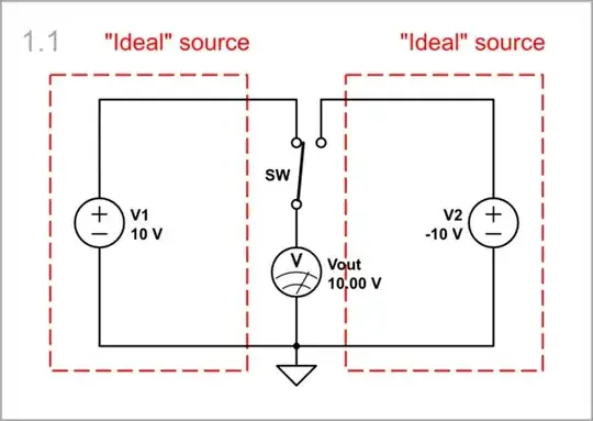
The point here is how to switch two voltages (eg 10 V and -10 V) to one input using a simple 2-terminal (SPST) switch. The usual solution is to use a 3-terminal (SPDT) switch, which first disconnects one voltage from the input and then connects the other voltage to the input.
simulate this circuit – Schematic created using CircuitLab
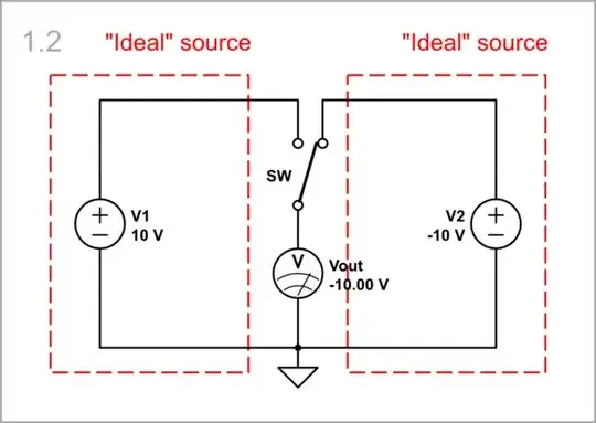
However, electronic switches (transistors) only have two terminals, and because of this, they long ago figured out how to make them switch two voltages. And here is what they came up with.
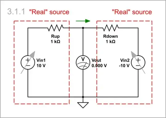
Instead of switching between two "strong" ("ideal") voltage sources with zero internal resistance, we can deliberately weaken one of them (by connecting a resistor in series) and simply connect the other to it. Thus the "strong" voltage source will dominate and impose its voltage so it will be applied to the input.
If we connect the resistor to the positive voltage source V1, figuratively speaking, it will "pull up" the output (trying to increase its voltage), and if SWdown is open, it will succeed...
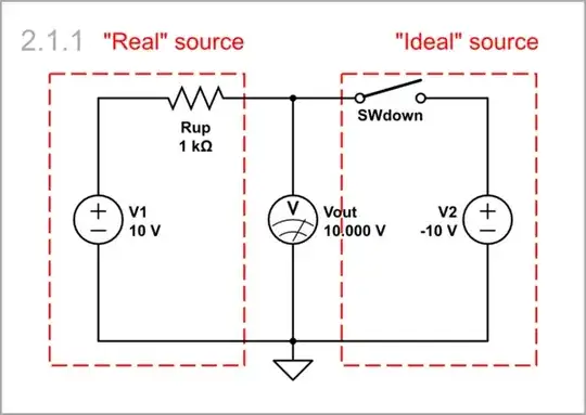
... but if SWdown is closed, the latter will "pull down" the GPIO to V2 (-10 V).

If we connect the resistor to the negative voltage source V2, it "pulls down" the output (trying to decrease its voltage), and if SWup is open, it will succeed...
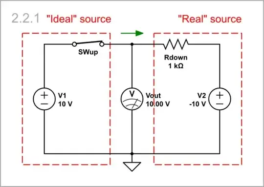
... but if SWup is closed, the latter will "pull up" the GPIO to V2 (10 V).

Inverting op-amp amplifiers use a configuration of two real voltage sources "pulling" the output in different directions (something like a "tug of war"). As a result, a virtual ground appears at the output.
Vin1 > Vin2: V1 "pulls up", and V2 "pulls down" Vout.
Vin1 < Vin2: V1 "pulls down", and V2 "pulls up" Vout.

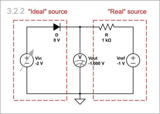
The same idea of "dominating ideal voltage source" can be seen in diode limiters where diodes play the role of switches.
Vin > Vref: The "stronger" forward-biased diode D directly connects Vin to the output.

Vin < Vref: If backward-biased, the "weaker" diode disconnects Vin from the output, and the latter remains connected to Vref.
Vin = -10 V ÷ 10 V: As you can see in the graph below, in the region from -10 V to 1 V, the output voltage is limited to the value of the reference voltage (-2 V); after that, it follows the input voltage.

Let's finally consider the OP's digital application of this idea.
The grounded switch (push button or open collector transistor) can be thought as an "ideal" voltage source...

... producing zero voltage when closed.

Similarly, the grounded "pull-down" resistor (the OP's circuit) can be considered as a real voltage source...

... producing zero voltage, and applying it through a resistance to the output.

In the picture i dont understand the purpose of the resistor (what it does), because there is no current so gpio 14 should read always low.
The OP's problem is now being clarified - it is about the role of the pull-down resistor and if it can be done without it. I prefer, instead of repeating the usual explanations, to demonstrate it with experiments (simulations).
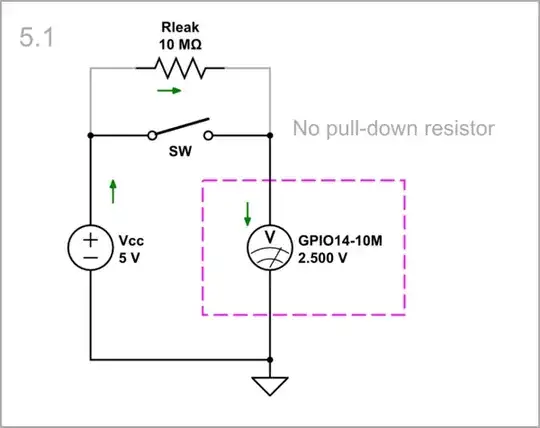
To see the benefit of the resistor, we need to examine the circuit in the presence of disturbance (leakage) - first, without a pull-down resistor, and then with the resistor. We can simulate the leak by means of a high (10 MΩ) resistor Rleak. Also, we can simulate the input resistance of the GRIO by setting such a high resistance (10 MΩ) in the CircuitLab parameters panel of the voltmeter.
No pull-down resistor: As you can see, in this case, Rleak and RGPIO form a voltage divider of two equal resistances of 10 MΩ with a ratio of 0.5. So, half of Vcc (2.5 V) is applied to GPIO, and not 0 V as you think.
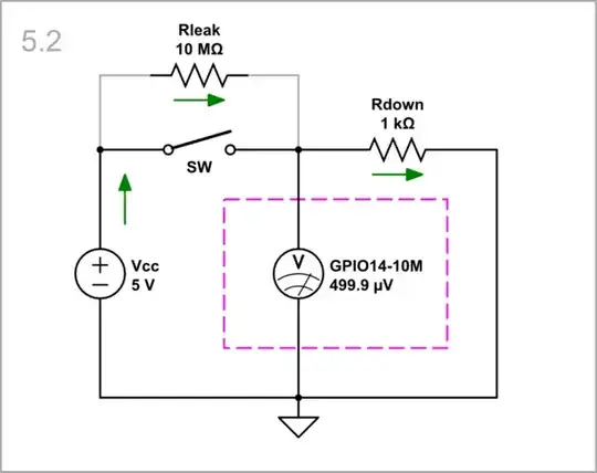
Pull-down resistor: Now let's connect the 1 kΩ Rdown. The divider's ratio decreases 10,000 times so only 0.5 mV (practically zero) is applied to GPIO.
The inputs of most microcontrollers and CMOS digital logic are extremely high impedance. They do not source or sink any significant current but sense the input voltage to decide the logic level.
If such an input is left unconnected it may acquire static charges causing its voltage to drift around between Ground and the positive supply. A pull-down resistor is used to ensure that an otherwise unconnected input is held at a valid Low logic level, but still allow it to be taken High when needed. Similarly, a pull-up resistor will hold an input High, but will allow it to be taken Low when desired.
It is important to realize that "no connection" does not necessarily mean "zero volts".
Contrary to what you say, the button has no ground except through the pull-down.
If you omit the pull-down, the GP14 will see 3.3V as logic high when button is pushed, but the problem is, when the button is not pushed, the GP14 will be connected to nowhere, so it is floating node and there is no well-defined potential.
And that is not allowed as the input can read it as pushed or not pushed, it is undefined and unreliable.
So the 3.3V voltage is provided to GP14 through button when it is pushed, and when button is not pushed, the resistor provides 0V ground to GP14.