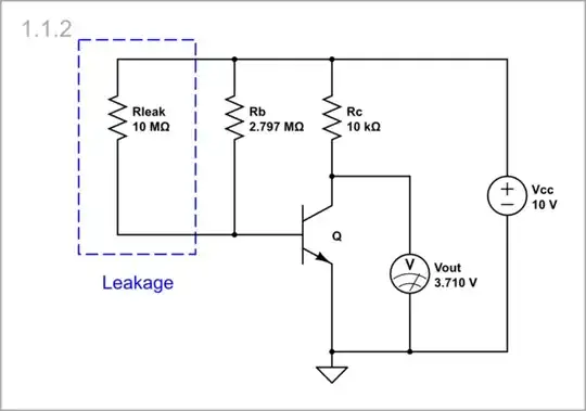
With the help of the CircuitLab experiments below we can study the behavior of the discussed circuits in case of leakage between the base and Vcc. In these experiments, we first set the quiescent output voltage to the middle (5 V) of the supply voltage Vcc. Next, we mimic the leakage by connecting a 10 MΩ resistor between Vcc and the transistor base.
Grounded emitter
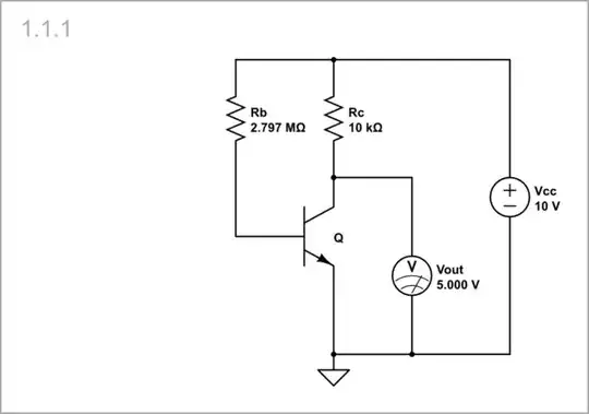
Let's begin with the simplest common-emitter stage with grounded emitter (the OP's circuit).
Bias resistor
The simple way to set the 5 V quiescent output voltage is to pass a current determined by a resistor Rb through the base-emitter junction of the transistor.
Undisturbed circuit: For this purpose, open the Rb parameters window and adjust its resistance looking at the voltmeter until its reading becomes 5 V. The resistance is high because of the high transistor beta and the relatively high collector resistor Rc.
simulate this circuit – Schematic created using CircuitLab
Positive leakage: Then connect the leakage resistor Rleak. Despite its high resistance, the output voltage drops significantly. The reason is that Rleak and Rb are connected in parallel, and the equivalent base resistance decreases significantly.
simulate this circuit
Bias voltage divider
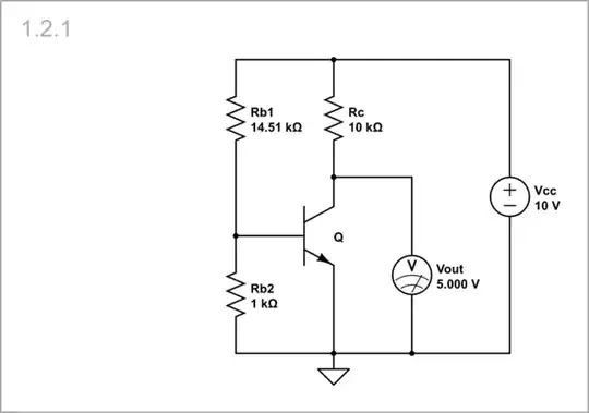
So, we decide to drive the transistor by voltage produced by a low-resistance voltage divider.
Undisturbed circuit: For this purpose, open the Rb2 parameters window and set its resistance about 1 kΩ. Then afjust Rb2 by looking at the voltmeter until its reading becomes 5 V.
simulate this circuit
Positive leakage: Now connect the leakage resistor. As you can see, now the output voltage drops slightly because the high-resistance Rleak is connected in parallel to the low-resistance Rb1, and the equivalent base resistance decreases slightly.

simulate this circuit
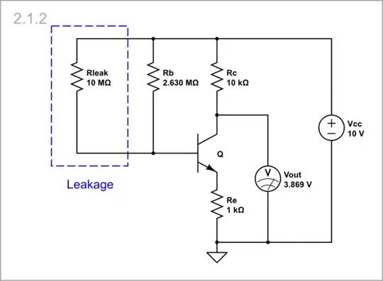
Emitter resistor
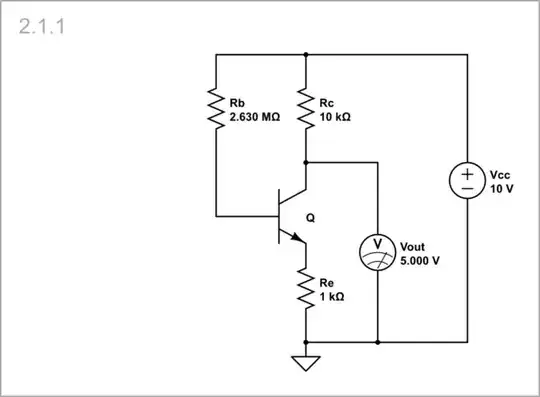
Let us now see how inserting a resistor into the emitter circuit improves the leakage resistance of the circuits.
Bias resistor
Undisturbed circuit
simulate this circuit
Positive leakage
simulate this circuit
Bias voltage divider
Undisturbed circuit

simulate this circuit
Positive leakage

simulate this circuit
