In some of the integrators in op-amps, I have seen a resistor in parallel with the capacitor in the feedback section.
Can someone tell me the purpose of the resistor in the RC of the integrator below.

In some of the integrators in op-amps, I have seen a resistor in parallel with the capacitor in the feedback section.
Can someone tell me the purpose of the resistor in the RC of the integrator below.
In some of the integrators in op-amps, I have seen a resistor in parallel with the capacitor in the feedback section.
While the feedback capacitor in the integrator provides the primary integration function, the feedback resistor ensures stability, controls the bandwidth, limits DC gain, provides protection against unwanted drift, and allows for control over the integration time constant.
So, let's explain these concepts:
Stability: The primary role of this resistor is to provide stability to the integrator circuit. Without ( R_f ), the integrator can integrate not only the desired input signal but also any DC offsets or low-frequency noise present at its input. Over time, these offsets or noise can cause the output voltage to drift to one of the supply rails, saturating the op-amp. The feedback resistor ( R_f ) provides a DC feedback path that helps prevent the output from drifting to the rails due to these unwanted signals.
Bandwidth Control: The resistor in combination with the integrating capacitor determines the frequency at which the circuit transitions from behaving as an integrator to behaving as an amplifier. At very low frequencies (below this transition frequency), the circuit behaves as an integrator. Above this transition frequency, the gain is determined by the ratio ( R_f/C ), where ( C ) is the integrating capacitor.
Reduce Gain at DC: An ideal integrator has infinite gain at DC (0 Hz). In real-world scenarios, this can cause issues. The resistor ( R_f ) ensures that the gain at DC is finite. The DC gain is set by the ratio ( R_f/R_1 ), where ( R_1 ) is the input resistor.
Protection: The resistor can also protect the op-amp from short-circuit conditions. Without the resistor, if the output is shorted to ground, the feedback through the capacitor could cause large currents to flow, potentially damaging the op-amp. The resistor limits this current.
Hope this helps.
Well, let's solve and show this mathematically. We are trying to analyze the following circuit (assuming an ideal opamp):
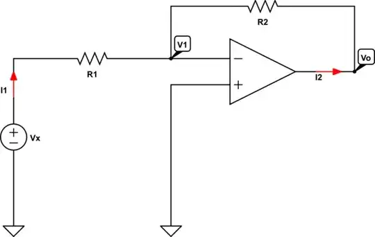
simulate this circuit – Schematic created using CircuitLab
When we use and apply KCL, we can write the following set of equations:
$$\text{I}_1+\text{I}_2=0\tag1$$
When we use and apply Ohm's law, we can write the following set of equations:
$$ \begin{cases} \text{I}_1=\frac{\text{V}_\text{x}-\text{V}_1}{\text{R}_1}\\ \\ \text{I}_2=\frac{\text{V}_\text{o}-\text{V}_1}{\text{R}_2} \end{cases}\tag2 $$
Substitute \$(2)\$ into \$(1)\$, in order to get:
$$\frac{\text{V}_\text{x}-\text{V}_1}{\text{R}_1}+\frac{\text{V}_\text{o}-\text{V}_1}{\text{R}_2}=0\tag3$$
Now, when we have an ideal opamp we know that \$\text{V}_+=\text{V}_-=\text{V}_1=0\$. So we can rewrite equation \$(3)\$ as follows:
$$\frac{\text{V}_\text{x}}{\text{R}_1}+\frac{\text{V}_\text{o}}{\text{R}_2}=0\tag4$$
Now, for the output voltage we get:
$$\text{V}_\text{o}=-\frac{\text{R}_2}{\text{R}_1}\cdot\text{V}_\text{x}\tag{5}$$
So, the transfer function is given by:
$$\mathcal{H}:=\frac{\text{V}_\text{o}}{\text{V}_\text{x}}=\frac{1}{\text{V}_\text{x}}\cdot\left(-\frac{\text{R}_2}{\text{R}_1}\cdot\text{V}_\text{x}\right)=-\frac{\text{R}_2}{\text{R}_1}\tag6$$
Now, applying this to your circuit we need to use (from now on I use the lower case letters for the function in the 'complex' s-domain where I used Laplace transform) the fact that the resistor \$\text{R}_2\$ is replaced by a capacitor, so:
$$\text{R}_2=\frac{1}{\text{sC}}\tag7$$
So, we get as the transfer function:
$$\mathcal{H}\left(\text{s}\right)=\frac{\text{v}_\text{o}\left(\text{s}\right)}{\text{v}_\text{x}\left(\text{s}\right)}=-\frac{1}{\text{sCR}_1}\tag8$$
Transforming back to the time domain, gives:
$$\text{V}_\text{o}\left(t\right)=-\frac{1}{\text{CR}_1}\int\limits_0^t\text{V}_\text{x}\left(t\right)\space\text{d}t\tag9$$
Now, when we replace \$\text{R}_2\$ with a resistor \$\text{R}_3\$ parallel to a capacitor we get:
$$\text{R}_2=\frac{\displaystyle\text{R}_3\cdot\frac{1}{\text{sC}}}{\displaystyle\text{R}_3+\frac{1}{\text{sC}}}=\frac{\text{R}_3}{1+\text{sCR}_3}\tag{10}$$
So, we get as the transfer function:
$$\mathcal{H}\left(\text{s}\right)=-\frac{1}{\text{R}_1}\cdot\frac{\text{R}_3}{1+\text{sCR}_3}=-\frac{\text{R}_3}{\text{R}_1+\text{sCR}_1\text{R}_3}=$$ $$-\frac{\frac{\text{R}_3}{\text{R}_3}}{\frac{\text{R}_1}{\text{R}_3}+\frac{\text{sCR}_1\text{R}_3}{\text{R}_3}}=-\frac{1}{\frac{\text{R}_1}{\text{R}_3}+\text{sCR}_1}\tag{11}$$
Now, when we have:
$$\frac{\text{R}_1}{\text{R}_3}\to0\tag{12}$$
We get a pure integrator back. This implies that \$\text{R}_3\to\infty\$.
In your case we can have \$\text{R}_3=10\text{R}_1\$, which gives:
$$\mathcal{H}\left(\text{s}\right)=-\frac{1}{\frac{\text{R}_1}{10\text{R}_1}+\text{sCR}_1}=-\frac{1}{\frac{1}{10}+\text{sCR}_1}\tag{13}$$
In order to guarantee feedback, even at very low frequencies, there is placed a resistor parallel to the capacitor. Because this circuit does not represent a pure (theoretical) integrator, in order to get as close as it can be to an integrator we need to choose the resistor as 'big' as possible, as shown.