2

I am trying to read and understand the below Raspberry Pi schematic to validate some of the basics I learned recently regarding passive components and how they are used in real schematics.

When I looked at it, there are bunch of capacitors in parallel almost everywhere (highlighted below in red boxes.) What is the significance for having so many parallel capacitors? Can they not just use their equivalent capacitor? I am just curious to know if there is more to it.
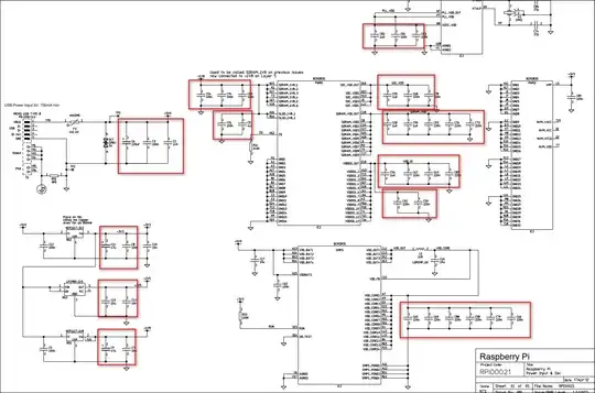
enter image description here

JRE
  • 71,321
  • 10
  • 107
  • 188
NTOS Linux
  • 111
  • 6
  • Thanks for link @user1850479, The answer in that post is informative. But my question is more around, why use so many capacitors in parallel instead of just using its equivalent capacitor. – NTOS Linux Oct 10 '23 at 17:24
  • @NTOSLinux the capacitors are not necessarily grouped together on the PCB – jsotola Oct 10 '23 at 17:40
  • The first answer to that question explains why capacitors have the value they do and why multiple may be required. Take a more careful look, and if you still don't understand, edit your question. – user1850479 Oct 10 '23 at 18:03
  • @user1850479, I did update the title of the question to better reflect my question. To be clear, The first answer did only explained it from the perspective of component availability(sourcing) and the component layout on the physical board. I am not looking for what should be the value of the capacitor to be used(as asked in the duplicate question you linked). Instead, I am looking for why we need to use multiple capacitors instead of single equivalent capacitor and are there any other technical reasons for it. – NTOS Linux Oct 11 '23 at 01:39
  • @user1850479, Also, Not sure why my question is marked as duplicate even though they are completely two different questions. What is interesting is, why should I edit a question if I don't understand the answer provided by a user. Shouldn't I consider other answers which makes more sense to me as an answer? which is what I did with the 2nd answer – NTOS Linux Oct 11 '23 at 01:39
  • This is a common question about a fundamental concept in EE that is discussed regularly on this board, so many people have asked and answered it before you. Just asking it again, even if you're still uncertain, will get it closed as a duplicate. Instead, if you can't make sense of the previous discussion, you should explain what you understood and what you did not and go from there. That will be a unique question and will lead to a unique answer that other people might also benefit from rather than just asking someone to summarize the same thing again. – user1850479 Oct 11 '23 at 02:23

2 Answers2

3

You'll notice that everywhere this is done the capacitors are from a power rail to ground. These are reservoir and bypass capacitors. The larger electrolytic ones are to store a bit of charge that can then be quickly drawn by the load when there is a sudden power draw. The lower value ones are to bypass the power rails and lower the impedance at higher frequencies.

Real capacitors aren't perfect, because of internal resistances and inductances different ones will have different impedance characteristics and self resonant frequencies, so they parallel several different types to try to lessen the effects of this. Electrolytic capacitors tend to not do so well at higher frequencies, while a ceramic capacitor that would have enough capacitance to serve as a reservoir cap would be large and expensive, combining one of each gives you the best of both worlds.

When you see two or more of the same values together they may be in physically different locations and just drawn together on the schematic, or they may be used to get a higher capacitance with lower impedance, as the capacitances in parallel add, while the parasitic resistances and inductances will be reduced. For example two 100nF capacitors with 0.1m\$\Omega\$ parasitic resistances in parallel will give you 200nF with 0.05m\$\Omega\$.

GodJihyo
  • 22,826
  • 1
  • 20
  • 58
  • Thanks for the answer, Now I learned what a bypass capacitor is http://www.learningaboutelectronics.com/Articles/What-is-a-bypass-capacitor.html. A follow up question, what capacitor values are considered "lower value" and what are considered "higher value"? – NTOS Linux Oct 10 '23 at 17:38
  • 1
    @NTOSLinux The higher value ones are going to be the electrolytics, these will generally be 1uF or higher, when you get into hundred or thousands of uF they're mostly filter caps to reduce ripple on rectified AC, for reservoir caps where your circuit is far from the regulators usually 10uF to maybe 470uF. Lower values will be ceramic or film, 1nF, 10nF, 100nF are common values, for RF you might see some below 1nF. When you see two or more of the same values together they may be in physically different locations and just drawn together on the schematic. – GodJihyo Oct 10 '23 at 18:50
  • @NTOSLinux See update to my answer. – GodJihyo Oct 10 '23 at 19:00
  • Thank you @GodJihyo – NTOS Linux Oct 10 '23 at 19:11
  • EEVblog #859 - Bypass Capacitor Tutorial https://www.youtube.com/watch?v=BcJ6UdDx1vg – NTOS Linux Oct 16 '23 at 19:32
1

One reason you might use multiple caps is to reduce the number of unique components in the design. Every unique component must be sourced, may go out of stock, requires a reel in the pick and place machine, etc. Using 2 100nF caps where a 200nF is called for is often cheaper (assuming you are already using 100nF's elsewhere).

When you see a small cap in parallel with a larger cap, that's usually because the smaller cap "works better" at high frequencies, and the large cap works better at low frequencies.

A chip may have multiple VIN pins, each of which requires its own decoupling capacitor, even though they are technically all on the same net. Adding to the confusion is the fact that the component in the schematic often has a different layout than the physical chip, so 2 pins which appear close might actually be separate, with separate decoupling. This is especially common with large ICs like MCUs.

Drew
  • 6,878
  • 2
  • 21
  • 40