Introduction
I have been "struggling" with this famous circuit solution for a long time to understand it. So far, I have only done it with my imagination and intuition, and because of that I have had a hard time convincing my opponents. My last attempt to do this was three years ago with the question, What is the idea behind the ingenious Widlar current limiter?
Now I will use CircuitLab to demonstrate "in practice" the correctness of my ideas. Indeed, with all these schematics and graphs, my answer is getting quite long, but the payoff for this will be the most valuable - understanding the circuit solution.
Just to clarify that understanding is not only to ascertain specific facts (for example, that the transistor Q2 begins conducting and diverting the base current of Q1 etc.) but to reveal why all this is done exactly this way, what is the idea behind the circuit.
Basic idea
Shown below is a current regulator circuit which ensures an almost constant current through R1 independent of Vin variations.
No, the idea is not to maintain a constant current through R1. The idea is to maintain a constant voltage across R1... and that is something very different as we will see in the schematic 9 below. There we will decrease twice the resistance and will see that the current is not constant but increases two times.
So the idea is to keep a constant current by keeping a constant voltage across a constant resistance. Let me now outline in several steps the evolution of the idea.
Idea evolution
Voltage divider
The simplest way to get the desired voltage Vout is with a (linear) voltage divider. However, it will be affected by the Vvar voltage variations. There is absolutely no feedback here.
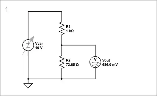
simulate this circuit – Schematic created using CircuitLab
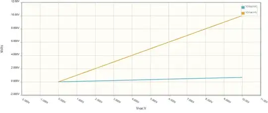
We see on the graph that when Vvar changes from 0 to 10 V, Vout changes from 0 to 686 mV which is unacceptable.
Diode voltage stabilizer
That is why, we decide to make a non-linear divider by replacing the lower resistor R2 with a diode D. Obviously, there is no negative feedback here (although the diode looks like a device with a voltage-type one).
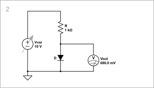
simulate this circuit
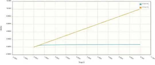
As we can see from the graph, Vout does not change noticeably.
Active-diode voltage stabilizer...
In integrated circuit topologies, the collector of a transistor is often connected to its base, and this configuration is called an "active diode". There is a voltage-type negative feedback here that makes the transistor decrease its collector voltage until the equilibrium is reached (here Vout = 686 mV).

simulate this circuit
As we can see from the graph, Vout almost does not change when Vvar changes.
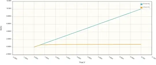
... with emitter follower feedback
The problem of the "diode" above is that a significant base current is diverted. We can decrease it many times by connecting a voltage buffer (emitter follower Q1) in the negative feedback path (between the Q2 collector and base).
simulate this circuit
The curve is more perfect (horizontal) than above... but we notice something new - the voltage has doubled (2VF).
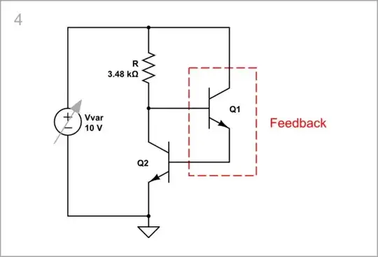
Emitter follower with inverting feedback
With the same success we can think of this configuration as an emitter follower (Q1) with an inverting amplifier (Q2) put in the feedback network (between the emitter and base).

simulate this circuit
Things are even more complicated (to the delight of those who love circuit mysteries:-) because the Q1 emitter is not only an output but also an input (as in a common-base stage). Its emitter voltage acts both on the Q1 emitter and on the Q1 base (through Q2).
2-transistor NFB amplifier
If we flip Q2 horizontally, we will see a 2-stage amplifier consisting of a cascaded common-emitter stage and a common-collector stage, and with applied negative feedback from the Q1 emitter to Q2 base. The input "signal" of this NFB system is the Q2 threshold voltage VF (about 0.7 V).

simulate this circuit
Low-current stabilizer
We ended up making a very good voltage stabilizer... but our goal was a current stabilizer. If we insert an ammeter into the Q1 collector circuit, we will see that a stable but very small collector current IL flows there (about 18 μA). But we need tens of mA of current. How do we increase it?

simulate this circuit
High-current stabilizer
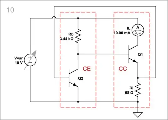
The solution is to put a resistor RI with low resistance (shunt) that will draw a significant current.
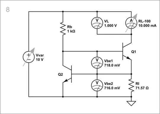
simulate this circuit
Vin = 0÷10 V: When Vvar changes, as usual, from zero to 10 V, the voltages stay almost constant...

... and the current through RI and RL too.

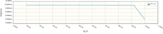
RL = 100÷1000 Ω: Now let's "provoke" our current source by varying the load resistance RL. I have done it by changing the internal ammeter resistance in the CircuitLab parameters window.

The current is constant, our current stabilizer is perfect (if only RL does not exceed 920 Ω when VL reaches 10 V, and the transistor saturates).
The role of RI
Finally, let's check the OP's statement above that "this current regulator circuit ensures an almost constant current through R1". For this purpose, we decrease twice RI, and see that the current does not stay constant but increases twice.

simulate this circuit
So "the circuit ensures a constant current through R1" (RI here) if its resistance is constant.
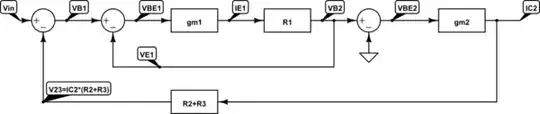
Another viewpoint
If we flip Q2 horizontally as in the schematic 6 above, we will see again a 2-stage amplifier with negative feedback that keeps up a constant voltage across the constant resistor RI so the current IL is constant.
simulate this circuit
Comparison
Since this circuit is claimed to be so good, let's check this "in practice". For greater persuasiveness, let's compare it (on the right) with the classical current source with emitter resistor (on the left) at various values of the input voltage.
Vvar = 10 V
Let's first set the nominal voltage of 10 V at which both circuits produce 10m A of current.
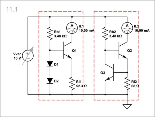
simulate this circuit
Vvar = 20 V
Then let's dramatically increase the voltage like doubling it. The advantage of our (OP's) circuit is obvious.
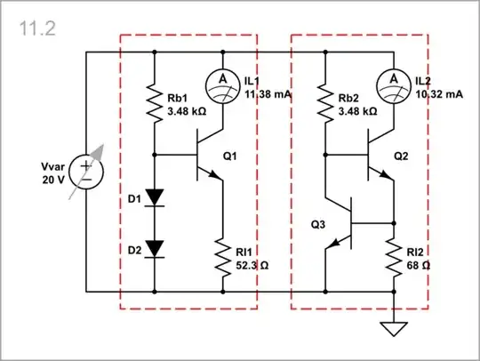
simulate this circuit
To convince ourselves even more, let's examine it graphically... same result again. If in doubt, you can triple, double, or increase the voltage as many times as you like; at least here it is possible, the simulator allows it.
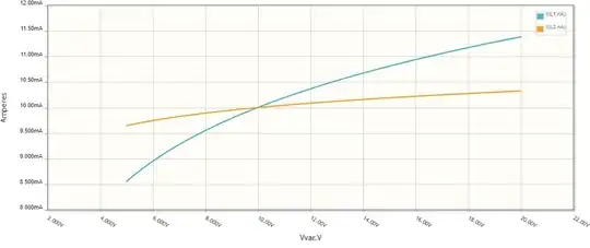
Conclusions
After the above experiments, we can outline the advantages of this constant-current circuit solution that make it widespread:
It automatically provides a 2VF reference voltage, half of which is lost in the Q1 base-emitter junction; the other half is applied to the emitter resistor RI.
Thus, the voltage across the load (the so-called compliance voltage) can almost reach the supply voltage (one VF less).
The second transistor (Q2) introduces additional loop gain which reduces the static error of this negative feedback circuit.


