2

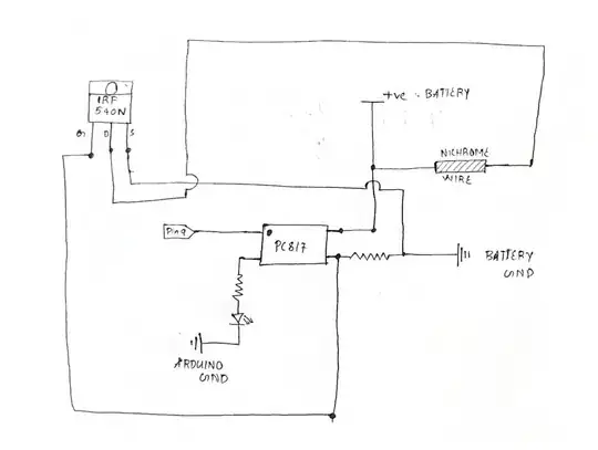
I want to make a nichrome wire red-hot on command. I planned to use an Arduino along with it. The basic idea was to use an optocoupler to isolate the nichrome wire section from the microcontroller side.

The Circuit I have tried is given below:

circuit

It seems like the circuit is not working. When I replace the load with an LED works as intended. When I give a pulse on the Arduino pin, the LED as the load is also glowing. With nichrome, it's not happening.

What am I missing here. How can I make such a system work together?

The battery in use is one 3.3V lipo battery for the nichrome wire. When I connect the battery directly to the nichrome wire, it gets red-hot.

I used a 10k resistor from PC817 to battery and 320 ohm from PC817 to the LED.
Lawliet
  • 21
  • 3
  • 1
    We don't even know the circuit parameters such as battery voltage or the resistor values, or Arduino GPIO voltage used to drive the optocoupler and LED in series, nor the LED voltage. So if you want an answer, provide the required details for anyone to reconstruct your experiment to find out why it does not work. – Justme Oct 09 '23 at 09:05
  • 1
    What is the battery voltage? If you connect gate straight to +ve do the wire heat up? – MiNiMe Oct 09 '23 at 09:06
  • Please answer all Justmes questions. You can update the schematics with the values of the components, it'll organize your question. Right now there are 2 resistors and a LED (what is the Vf) that are incognito. – MiNiMe Oct 09 '23 at 09:18
  • 1
    Hello Lawliet and welcome. You might take a minute to read through the notes about good circuit diagrams, the universal language for explaining a circuit. What you have might be very helpful for wiring (showing pinouts etc) but a person who doesn't know what a PC817 or an IRF540N are won't know anything about your circuit. – jonathanjo Oct 09 '23 at 09:19

2 Answers2

3

Looking at the IRF540N datasheet, we can see that the gate threshold voltage is in the min-max range of 2V-4V, and the quoted Ron is at 10V Vgs

You are driving the gate from the 3V3 battery via a coupler, and depending on the coupler details are probably only applying 2-3V to the gate.

As a result, you are almost certainly not turning the N-FET on fully, definitely not with enough voltage to deliver the speced Ron.

There are lots of N-FET designed for direct logic drive, so just select one that will deliver your required Ron with the gate drive you have available.

colintd
  • 7,833
  • 1
  • 11
  • 34
  • If I have a direct logic drive N-FET, then the ground of nichrome wire and the Arduino will be common. and when nichrome wire is short circuited the Arduino is tripping. – Lawliet Oct 10 '23 at 00:22
  • 1
    I'm not saying you remove the optocoupler, rather than you should choose a fet which is designed for direct logic drive, because that will have a very low gate drive voltage for full Ron performance – colintd Oct 10 '23 at 06:22
1

As well as using a logic-level MOSFET (pick one that has Rds(on) with an acceptable maximum specified at Vgs = 2.5V or so), by putting an LED in series with the optocoupler IR LED you're probably not getting much current.

It would be better to drive them in parallel from the GPIO, each with an individual series resistor.

Spehro Pefhany
  • 397,265
  • 22
  • 337
  • 893