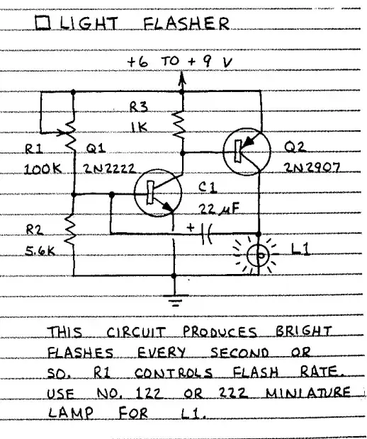
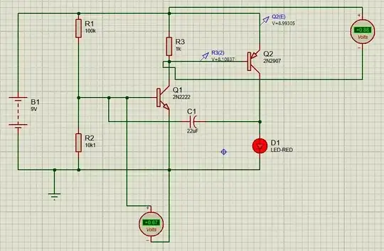
Hi I am new to electronics. But I do understand some of the basics of the resistors/capacitors/transistors. While reading Getting started in electronics by Forrest M I have come across below circuit. As per its description it says the light(L1) will be flashing. But as far as I analyzed the circuit, it appears that Q1 Vbe will be around .5V and turns on both Q1 and Q2 completing the outer loop and turns the L1 always on. I also verified this in Proteus. Can someone explain if my analysis is incorrect or if I am missing something.
- 111
- 6
-
1An LED is not the same thing as a lamp. Try substituting a 100 Ω resistor for the LED. – Dave Tweed Oct 07 '23 at 03:02
-
I don't actually like the arrangement. Aside from the lamp issue already discussed, this circuit essentially ties $V_{\text{CC}}$ to ground through the $V{\text{BE}}$ of the PNP and saturated $V{_\text{CE}}$ of the NPN, with the only thing limiting the current being $r_b^{:'}$ of the PNP. This value may be about $20:\Omega$ for a peak current close to $\frac{9:\text{V}-800:\text{mV}-400:\text{mV}}{20:\Omega}=390:\text{mA}$. That's completely unnecessary, completely unmanaged, and therefore not a good design. There's just no need for this kind of carelessness. – periblepsis Oct 07 '23 at 03:25
-
But I agree with @Dave. The inserted $100:\Omega$ in series with the LED will help a lot. I'd also recommend an added PNP base resistor to limit that current. Perhaps a $3.9:\text{k}\Omega$ would be about right. And, of course, make sure that $V_{_\text{TH}}$ of the base resistor pair for the NPN is around $700:\text{mV}$. Something like this. – periblepsis Oct 07 '23 at 03:27
-
The $V_{_\text{TH}}$ is critical. Too high and the LED just stays on. Too low and there isn't enough "juice". You have to hit a sweet spot where the loop gain can transition through exactly 1, via the work that the capacitor does for you with its positive feedback each half-cycle. – periblepsis Oct 07 '23 at 03:36
-
@NTOS If you want to build something that is somewhat better designed, try this. Adjust the NPN emitter capacitor and resistor for your timing needs near your specified vlaue. Period should be on the order of $1:\tau$. – periblepsis Oct 07 '23 at 03:51
-
Take a look here https://electronics.stackexchange.com/questions/338128/is-this-an-astable-multivibrator/338163#338163 – G36 Oct 07 '23 at 06:48
-
@G36 Thanks for the explanation in that question. I kind of got the explanation but looks like I need more exposure to these sort of circuits to better analyze them. Any pointers in general to get good at analyzing these circuits? Every time I read some well known books they concentrate mostly on circuits involving AC signals. Also what bothers me the most is, most of the textbooks only teaches the basic principles of these components but care less about how they are applied. Any suggestions will help my understanding. Thanks again for your response. – NTOS Linux Oct 07 '23 at 07:27
1 Answers
Without Q1 connected, R1 and R2 form a voltage divider. Also, R2 is the charging path for C1. For the circuit to oscillate, this node must be far enough below Q1's Vbe to assure it is turned off when C1 is charged up. At 10K, R2 is too large in the sim. Change it to 5.6 K, and reduce the battery to 6 V. This will assure that the Q1 base voltage can get low enough to turn it off.
Also, you cannot substitute an LED (D1) for an incandescent bulb (L1). The voltage drop across D1 is only around 2 V, because that's what the forward voltage (Vf) of a typical small red LED is. A light bulb will have the full 9 V across it when flashing.
If you do want to stick with the LED, it will need a current-limiting resistor in series with it.
A common problem with oscillator circuits in simulators is that they fail to start because all of the components are theoretically perfect with no noise. Most simulators have tricks you can use to get things to start oscillating, such as ramping up a supply voltage over a few milliseconds.
UPDATE:
When power is first applied, C1 has no charge, and zero volts across it. The resistance of the bulb holds the right side near GND. R1 starts charging up C1 until the left side is above the Q1 Vbe. Q1 comes on, Q2 comes on, the light comes on, and the oscillator is running. Q2 pulls the right side of C1 up to Vcc, which pulls the left side above Vcc. Now, R1 and R2 (mostly R2) pulls C1 down toward GND.
Note that C1 is charging (the voltage across it is increasing) when the left side of it is pulled down toward GND by R2. C1 is charged when Q1, Q2, and the light are on. When R2 pulls C1 below the Q1 Vbe, Q1 turns off. This turns off Q1, "releasing" the lightbulb. The resistance of the incandescent bulb is much less than R1, so it pulls the right side of C1 to GND. This pulls the left side below GND. Now, C1 discharges through R1 and R2 as the left side increases up to GND. Eventually, R1 pulls the Q1 base above its own Vbe, Q1 turns on, Q2 turns on, the light turns on, and the cycle repeats.
The light cannot be an LED because an LED does not have a DC resistance all the way down to 0 V across it; it stops conducting when the voltage across drops below its Vf.
This type of circuit is called a relaxation oscillator. A common feature (or bug - ?) is that the period of the first cycle is different from all succeeding cycles. This is because it is the only time when the timing capacitor has zero charge when the light changes state. Depending on the circuit, once the oscillator is running the timing capacitor might never nave 0 V across it again. The most common example of this is the 555 astable circuit.
Also, look into something called the Thevenin equivalent. This is the math behind how R1, R2, and Vcc "appear" to the base of Q1.
- 19,998
- 1
- 13
- 32
-
Thanks for the response, one dumb question. When C1 is charged by maintaining Q1 in off state, what makes it get discharged? Is it possible for you to elaborate the explanation on one complete on/off cycle for the above circuit? Your help is much appreciated. – NTOS Linux Oct 07 '23 at 06:45
-
-

