I bought a CNC control board equipped with Teensy 4.1 and the T41U5XBB to replace the mks dlc32. I am sorry to discover that the endstop pins of the new board only accept NPN sensors, both NO and NC. My current system has 3 PNP NO sensors that work well. I'm looking on the internet and I find that I need to add an npn transistor to the pnp output but I can't figure out how to do it...The NPN based PNP emitter via resistor, NPN pin collector and NPN emitter to GND? Thank you
Asked
Active
Viewed 119 times
1
-
1Do you want a PNP NO output to be translated into an NPN NO output? (I'm not sure.) – periblepsis Oct 02 '23 at 14:50
-
1yes, from the pnp sensor I have to go to pin with NPN – Biagio Di Stefano Oct 02 '23 at 14:55
-
2Sounds easy. You will get an answer soon. Not necessarily from me. But it is just an NPN with its base tied to the PNP collector via a resistor, with an added pull-down for the NPN base. – periblepsis Oct 02 '23 at 15:06
-
The sensor is a PNP NO fork opto with 3 5V-S-G wires. I should bring the S output to controller pin but with NPN logic – Biagio Di Stefano Oct 02 '23 at 15:20
1 Answers
1
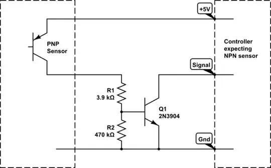
simulate this circuit – Schematic created using CircuitLab
R1 limits the on-state current in the sensor to about 1 mA. Adjust as required for different supply voltages.
R2 keeps sensor leakage currents as high as 1 µA from activating Q1.
Q1 can be any generic NPN transistor.
Dave Tweed
- 172,781
- 17
- 234
- 402
-
Thanks for the answer... on X and Y I have PNP NO opto fork sensors which I currently power from the controller with 5v and the example you provided is perfect. On the Z axis instead I mounted an inductive device that accepts 6-36v, always PNP NO. In this case I feed it e.g. 9v from external power supply and on the black I measure 9v when engaged. to bring it (as PNP) to the controller I had to make a 4.7k+4.7k voltage divider between S (black) and G (blue). – Biagio Di Stefano Oct 02 '23 at 17:16
-
This way I get about 4.5V to send to the esp32 pin. To handle this inductive situation do I use the diagram provided, keep the resistive divider and bring my pin to the base of the NPN? Naturally I combine the masses of external power supply and controller. – Biagio Di Stefano Oct 02 '23 at 17:17
-
I'd really need to see a diagram of your Z-axis setup to be sure, but it seems to me that you should be able to eliminate the voltage divider, and just use a larger value for R1 (e.g., 10k or so) in the circuit above for the Z-axis sensor. This keeps the sensor current at around 1 mA with the 9 V supply. – Dave Tweed Oct 02 '23 at 19:11