2

I want to derive the input impedance of this JFET circuit :

schematic

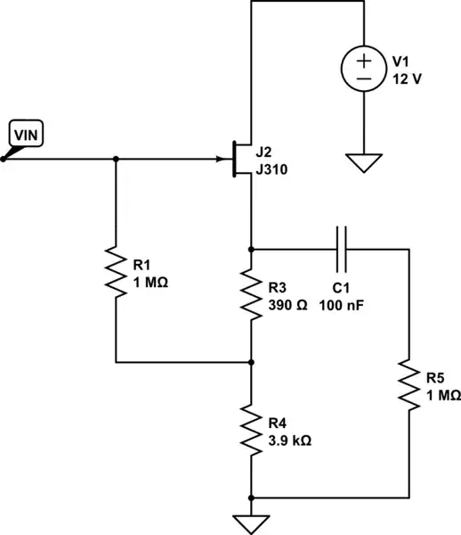
simulate this circuit – Schematic created using CircuitLab

What is the method in order to derive the input impedance of this circuit?

here is the small signal but I haven't been able to deduce the equation of the input impedance

schematic

simulate this circuit

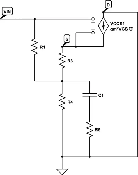
by neglecting output load :

Zi=Vin/i

i=(Vgs+gm*Vgs*R3)/R1

Vin=Vgs*(1+gm*R3+gm*R4)+i*R4 = Vgs*(1+gm*R3+gm*R4)+(Vgs+gm*Vgs*R3)/R1*R4

Zi=((1+gm*R3+gm*R4)+(1+gm*R3)/R1*R4)/((1+gm*R3)/R1)

There is something wrong with these equations but I can't see my mistake...

exolune
  • 59
  • 2
  • Here you will find the answer https://electronics.stackexchange.com/questions/372071/r-in-and-r-out-mosfet-calrification/372094#372094 – G36 Sep 23 '23 at 15:32
  • You have to draw the equivalent circuit for incremental signals at the center of the band . Once this is done, analyze the circuit and find the input impedance by applying a test voltage source to the input. – Franc Sep 23 '23 at 15:33
  • 2
    "derivate" is a result of a calculation. I believe you want to "derive" the input impedance. Have you thought about using a simulation tool? – Andy aka Sep 23 '23 at 15:40
  • We see that R1 resistor current determines the Rin. Rin = Vin/I_R1 So we need to find the I1 resistor current. JFET gate current is 0A. So I_R1 current is: $$I_1 = \frac{V_{IN} - V_{OUT}\frac{R_4}{R_3 + R_4}}{R_1}$$ Additionally, we know that $V_{OUT} = A_V * V_{IN}$ So if we combine all the information we get Zin is equal to $$Z_{IN} = \frac{R_1}{1 - A_V \times \frac{R_4}{R_3 + R_4}}$$ – G36 Sep 24 '23 at 07:53
  • I see that you did manage to find the Zin. Your equation is correct. Good job. – G36 Sep 24 '23 at 12:44
  • This technique of increasing Zinc is called bootstrapping. Take a look here https://electronics.stackexchange.com/questions/586839/explanation-about-op-amp-bias-resistor-and-bootstrapping/586859#586859. And in your circuit, we have the same situation. But this time Zin ≈ R1/(1 - Av * R4/(R3 + R4)) where Av ≈ ((R3 + R4)||RL)/( 1/gm + (R3 + R4)||RL) – G36 Sep 24 '23 at 12:52
  • G36, thanks for your explanations, I didn't know that feedback was called bootstraping. – exolune Sep 25 '23 at 18:43

1 Answers1

0

You can derive the input impedance as suggested in the links in the comments. Deriving a useful function over frequency is more involved, thus, using a simulator is a more expedient method. The accuracy of the simulation depends on the accuracy of the transistor model.

The simulation below shows how you can do this in LTspice. enter image description here

The red trace is the input capacitance which is about 2.1 pF which affects the impedance (|Z|) above 5 kHz.

qrk
  • 9,494
  • 1
  • 7
  • 26
  • qrk Thanks a lot for your reply, you're right the result is 6Mohms but I can't find it by equation from my small signal model – exolune Sep 23 '23 at 22:05
  • See the update in the first post for equations and small signal model – exolune Sep 24 '23 at 00:14