0

I have been in the process of remaking Ben Eater's 8-bit-computer, and have a few questions. I got to the part where the clock, which consists of 3x 555 timer, is connected with logic gates. However, even after testing every IC and ensuring it works, I do not get the desired output.

Pin 3 of the astable one is connected to pin 1 of the AND gate. Pin 3 of the astable one is connected to pin 2 of the AND gate, and also via an inverter to to pin 4 of the AND gate. Pin 3 of the monostable one is connected to pin 5 of the AND.

The only differences between my circuit and the one Ben Eater made are the following:

  1. The bistable 555 isn't controlled by a button, but by manually connecting either the trigger pin or the reset pin to VCC.
  2. The SN74LS32, which is sadly not available where I'm from, has been replaced by the 74HC32, since I'm new to electronics I'm not quite sure if this is a problem. Again, all of the ICs work fine and everything is connected as in the tutorial.
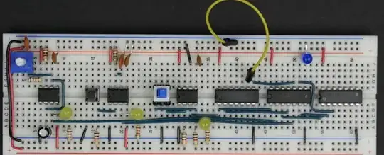
Thanks in advance! that's Ben Eater's circuit

That's my circuit

lukasm06
  • 1
  • 1
  • 2
    Please add a proper schematic. Also describe what you mean with not getting the desired output (while according to you, all ICs work fine). – StarCat Sep 23 '23 at 07:54
  • 3
    Sorry, but we don't know what that bunch of chips and wires should look like and do to get desired output and what it does instead when you say you don't get the desired output. Is there schematics? There is no piece of info to determine what is correct and what is wrong. Also, LS and HC chips may not be interchangeable due to their differences. There are no bypass caps either on the chips. – Justme Sep 23 '23 at 07:55
  • https://youtu.be/SmQ5K7UQPMM?si=3jjQ-CstkU3rumVU Here around minute 9 is what the circuit should do. However, my LED doesn't turn on regardless of the 555 outputs. Sorry for not providing enough info. – lukasm06 Sep 23 '23 at 09:14
  • This may be of use: https://electronics.stackexchange.com/questions/572431/astable-555-circuit-always-on-not-oscillating/572438#572438 – hacktastical Sep 23 '23 at 09:17
  • The markings on the ICs are unreadable in your included pictures. That, combined with the absence of schematics, makes it very hard to help you. – StarCat Sep 23 '23 at 13:02
  • https://eater.net/8bit/clock The left 555 is a free-running oscillator. The middle 555 is a one-shot for single stepping. The right 555 is a debouncer for the clock select switch. Which portion isn't working? – Mattman944 Sep 23 '23 at 14:03
  • 1
    Note that few people here will watch links to videos. I don't want to watch a ten minute video for something that can be described in a few sentences and a few pictures. – Mattman944 Sep 23 '23 at 14:05

0 Answers0