6

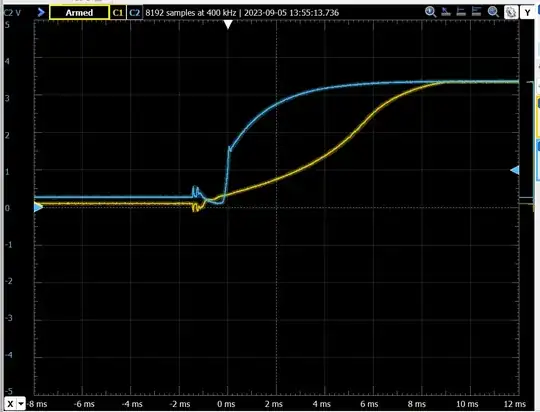
Below, I have waveforms showing power-up on the 3.3 V rail of two otherwise-identical microcontroller boards, the only difference being two different 3.3 V DC-DC switching regulators. In the blue, the V7803-1000 and in the yellow, the VX7803-1000. According to their respective datasheets, both regulators have nearly-identical specs, but the VX takes significantly more time to stabilize after power-up, and in fact exceeds the rising slope requirement of the microcontroller (min 1.9 V/ms), badly enough to cause boot failure.

More data points: I tested the K7803-1000R3 which resulted in a curve almost identical to the yellow curve below. After a few hours reviewing other regulators, I only found two companies that list rise time in a datasheet: TI's TPSM84203 intentionally provides a 5-ms soft start (0.66 V/ms), and the new-to-me XP Power sells the JCA0624S03 which has comes closest at 0.94 V/ms.

Waveforms of two different DC-DC converters on otherwise-identical microcontroller boards.

What causes the significant difference between rising slope on two apparently "identical-spec" DC-DC converters? Is there any way, short of purchasing and physically testing potentially hundreds of equivalent converters, to determine which will output a rising slope that meets the spec, since few datasheets appear to provide information about start-up rise time? Is there a better way for a 3.3 V power rail to meet a minimum 1.9 V/ms rise time, that renders the choice of regulator moot?
Matt S
  • 3,512
  • 2
  • 11
  • 34

4 Answers4

14

A better approach might be to design your microcontroller circuit to accept any rise time, which might involve using an external supervisory reset chip.

Or if that's not possible use a power supply sequencing chip to switch the power after a worst-case delay time.

Spehro Pefhany
  • 397,265
  • 22
  • 337
  • 893
5

One option is to use a load switch that you turn on after the DC-DC output is stable.

Many DC-DC converter ICs will show a typical startup waveform on the datasheet, or you can see it in the documentation for their "demo" boards. Of course that's only valid for the test circuit and conditions given.

Others have adjustable soft-start times, so you could potentially pick a converter with that feature.

Another option is to download the simulation model provided by the manufacturer and see what the startup waveform looks like in simulation before committing to hardware.

Of course most of the above applies if you use a DC-DC converter/controller IC. If you want to use a module you may not have as many choices.

Since the CUI modules don't give schematics showing which controller/converter is used internally, it's difficult to say why the startup times are different between the two.

John D
  • 23,824
  • 1
  • 41
  • 61
4

exceeds the rising slope requirement of the microcontroller (min 1.9 V/ms)

That "requirement" is in essence an admission of poor performance of the POR circuit. The MCU won't get damaged with lower rise time, and you can test that of course. Just keep it in reset with an external part until the power is good. If the SMPS has a power-good output, so much the better :)

2

Typically, microcontroller power-on reset circuits are designed to hold the CPU in reset for a certain amount of time after the input voltage reaches a certain threshold. Often, both delays and logic thresholds, as well as the minimum voltage at which a controller can operate reliably, may be affected by process variations, but it may be possible for a manufacturer to influence one in response to changes in the other. If the spec says 1.9V/ms, that means that the startup delay, reset threshold, and minimum operating voltage will be such that multiplying the startup delay by 1.9V/ms and adding the start-timing-the-reset threshold will yield a voltage which reaches the minimum required for reliable operation.

On many parts, the power supply voltage may vary harmlessly in arbitrary fashion within the range specified by absolute maximum ratings, while the reset pin is asserted, provided that the voltage is within the valid operating region when the reset pin is released, and remains there unless/until the pin is reasserted or a situation arises where nothing a chip might do would be considered unacceptable (e.g. because the device is being powered down, and nobody would care if the device turns on lights, beeps, etc. for a brief moment).

If the supply voltage might take awhile to stabilize when powering on a device, some means external to the microcontroller will likely be needed to ensure the device doesn't start until the supply is stable, but adding such means would avoid the need to clean up the startup voltage ramp.

supercat
  • 46,736
  • 3
  • 87
  • 148
  • This is clearly the right answer for this question in general, but after experimenting on my board: asserting the reset pin on power-up and then deasserting after a stable voltage is achieved, the chip still somehow locks up. (?) In this particular case, something is preventing boot-up in such a way that even the reset signal is ignored. Unfortunately it's looking like I'll either need to hope the perpetually low-stock V7803 remains available, or I'll be convincing the team that the power supply needs a significant redesign... – Matt S Sep 07 '23 at 13:13
  • 2
    @MattS I strongly suspect you have a separate issue here. Sure, something may be preventing boot-up - but it's not necessarily the PSU which is the cause. It could even be a different PSU-related issue, for instance if your boot configuration enables a bunch of microcontroller features which cause enough of a current draw spike to be a problem for that PSU (or for that PSU on startup). – Graham Sep 07 '23 at 13:22
  • 2
    @MattS ... FYI too, engineers I work with tend to keep reset asserted for a while after that stable voltage happens, maybe as much as 100ms. Merely crossing a threshold isn't enough to confirm we're ready to go - it needs to stay up and stable for a while before we assume we're good to go. – Graham Sep 07 '23 at 13:23
  • @Graham It's a difficult one, for sure. Of the recent 50-board production run with the VX7803 supplies, 39 function properly ("good") and 11 require a quick power cycle at startup ("bad"). A "good" board boots with a VX supply from a "bad" board, and a "bad" board will not boot using the VX supply from the "good" board, supporting your hypothesis. However, after swapping in a V7803 supply, the "bad" boards work 100% of the time. I think there's something in the uC start procedure that's getting mucked by the slow start, but it's due to process variation in the uC or its supporting components. – Matt S Sep 07 '23 at 13:48
  • @Graham FWIW I'm physically shorting the RST pin to ground by hand, so it's well over 100 ms. The boot also fails in the uC default (erased) configuration (an operational device will activate over USB and appear in Device Manager) despite having no peripherals enabled. I also wrote a bare bones firmware (22 lines of asm) that blinks an LED in the reset handler; the uC doesn't even get that far. The uC is a SAMS70 - the datasheet is generally very good at providing layout and component selection guidance for the rails, but unfortunately lacks suggestions for actually supplying the power. – Matt S Sep 07 '23 at 13:57