The following is a rough-and-ready technique for experiments, and if you check all the voltages carefully, might be suitable for some designs.
One of the simplest methods, suitable for UARTs and short distances, is simply divide down the higher volts with a resistor divider. In this particular case, there's not any real noise margin, but for an experiment on the bench you can try this.
You have to check the exact details of the given systems
- UNO Input: With a ATMega328P at 5V (such as in your Arduino Uno), the 3.3V signal is adequate as a high signal, where a the high threshold is 0.6 VCC, ie 3.0 V. The minimum promised logic high voltage, VOH min, on some models Raspberry is also 3.0V (ref), so it will work on the bench but you'd probably not want to do this in production. On some models it's only 2.4V, which may well not be enough to drive the ATMega.
- Raspberry Pi Input In the other direction, you should check on your exact model in the Raspberry Pi datasheets, but on a 3.3V system you have assume that VIH max is no higher than VCC, ie 3.3V. For the RPi4 these values are unhelpfully given "TBD", though say "VDD_IO is the GPIO bank voltage which is tied to the on-board 3.3V supply." This appears to be the same as the CM4, where there is a voltage reference for GPIO, VGPIO_VREF, which can be 1.8V or 3.3V. On the CM4IO board, it's 3.3V, giving VIL min is 2.0V and max is VGPIO_VREF, ie VCC, ie 3.3V. See table 4 of CM4 datasheet, VGPIO_VREF is set by R5 on Fig. 5, of CM4IO datasheet. Some more values are given in the overview documentation.
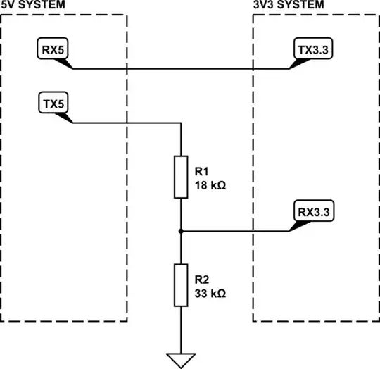
simulate this circuit – Schematic created using CircuitLab
Calculating the resistors:
5 V * 33000 / (18000 + 33000) = 3.24V
ATMega328P
Note that the reset and crystal pins have different thresholds.
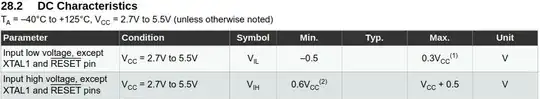
From ATMega328P datasheet


