1

I know questions on SR latch and FF has come up fairly often and I've already seen answers that made me understand better how this device work.

However, I still have a doubt when both input S and R are 0: from the thruth table it is known that the outputs are the same thus indicating that in this case the SR acts like a memory, so it is storing the information. I can't really get how we deduce something like this when we power up the device.

I am considering the case of the SR being built with two NOR gates, that being enter image description here

I am also aware about the race condition that comes up due to the gates not being identical, so one will win over another. Considering this, I am trying to start with the idea of the latch on power up: suppose we give S = R = 0, what will be the output? How does the latch "holds output" if there was no previous output? Will it be undefined and, if that is the case, can we say the latch is still "holding the output"?

aghin00
  • 23
  • 3

3 Answers3

2

Actually your truth table has a slight problem.

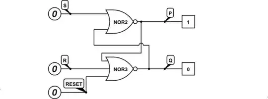
Since a NOR gate output is LOW if either one is or both inputs are HIGH, so your SR latch will output P=Q=LOW if S=R=HIGH. It is a valid input for the circuit, causing valid output, if you don't consider the circuit as an SR latch.

Also you think the circuit as if it were somehow magically ideal, with either logic 0 or 1 digital inputs and outputs, and somehow quantized in time where it has a current state and next state like it was driven with a clock tick.

That only works in ideal world of mathematics and logic.

As you think of the circuit behaviour when power supply is turned on, please understand that the supply will also not be just off and then suddenly on at the next instant, that is physically impossible in real world.

In real world the logic gate is made of analog transistors and the signals are analog. The supply will be an analog signal too. Analog signals have finite bandwidth, meaning they rise and fall at some rate so the transitions happen in some time, as it would take infinite amount of bandwidth and energy to transition at infinitely fast rate in no time at all.

So holding the inputs S=R=LOW while turning the power supply on, the outputs don't have a valid state as the transistors don't have a valid supply voltage at first. Only when supply rises to high enough level, the transistors start to turn on and starting to pull the output PMOS transistors high.

So at some point the high output is high enough to turn on the output NMOS transistor, so for a moment there will be transistors pulling output both high and low until the supply voltage is high enough for the transistors to work strongly enough and end up into a stable state, which is basically random but due to transistor manufacturing tolerances and internal structures such as stray capacitances a certain logic gate may always end up in same state if you power it on identically multiple times.

So it does not hold any previous output as there is no previous state it is set to. That's why many circuits and ICs have a "reset" pin and a system may have a "powet on reset" circuit to make sure that all gates are "set" or "reset" on powering up to correct state as required by the system so the system does not start running on some random power-up state.

I assume unbuffered CMOS NOR gate in my example but there are also other logic families such as NMOS, PMOS, TTL, etc, so how a logic gate behaves depends on how it is built.

Justme
  • 147,557
  • 4
  • 113
  • 291
  • Thank you for the example aut transistor-level. I apologize for the truth table, it is not mine but I needed one from google so I picked that one. I know that it is incorrect to sat valid input as the circuit works perfectly, just not at logic level. Your answer was helpful. – aghin00 Aug 29 '23 at 20:19
1

Because of mini-micro variations in individual transistors, even ones on the same IC die, the power-on state of the circuit is unpredictable. Worse that that, even if a circuit powers up in the same whatever state 99 times in a row, that is no guarantee that the 100th time will be the same.

Yes, the latch still is holding its output. The current output state is not dependent on any previous state. The circuit is not clocked, so the outputs reflect the condition of the inputs within nanoseconds of any input change. Holding the output correctly, and powering up consistently, are two very different things.

Note that it always is a very bad thing to leave logic gate inputs undetermined. They always should be driven with valid voltage levels or terminated to either Vcc or GND with appropriate resistors. If you are asking about your circuit as shown sitting out on a bench with no inputs, then the outputs will reflect the input conditions, down to nanovolts, when the operating voltage was high enough for the gate input stages to discern highness and lowness.

UPDATE:

Your truth table has a group of output states, and corresponding input states (conditions) that cause those outputs. IOW, the outputs reflect the inputs; the outputs indicate the inputs.

AnalogKid
  • 19,998
  • 1
  • 13
  • 32
  • What do you mean by “reflecting the input”? Also, could you elaborate more this part: “then the outputs will reflect the input conditions, down to nanovolts, when the operating voltage was high enough for the gate input stages to discern highness and lowness”? – aghin00 Aug 29 '23 at 20:08
1

I can't really get how we deduce something like this when we power up the device.

Correct: because nobody can deduce it, not only you :)

The start-up state of an SR latch as you've drawn it is indeterminate. Until you first set or reset it, it can be outputting either 0 or 1. It will be a stable state, just unknown.

Considering this, I am trying to start with the idea of the latch on power up: suppose we give S = R = 0, what will be the output?

The answer is simple, but perhaps unexpected: It will certainly be either 0 or 1. One or the other. Not invalid, just indeterminate: a valid logic state, drawn from a random distribution. The SR latch will take a tiny bit of time for the output to settle on power-up - on the order of its propagation delay.

Some latches reliably act as random "coin toss" generators, usually slightly biased towards either 1 or 0. Others are so heavily biased that it may take thousands, million or billions of power cycles to see a different output than what it was originally.

It is possible to design latches that come up reliably in a desired initial state. It is hard to imagine how it'd be possible, because actual physical latches are not built up out of gates, but out of CMOS devices (or bipolar devices in TTL and ECL). Well-performing SR latches only logically act like they had two cross-connected gates. They may be implemented with a circuit that is different than two separate gates connected together. Once you're at transistor level, startup circuits are possible that will reliably initialize the latch on power-up.

If you limit yourself only to gate-level representations, a lot of the common techniques used to implement digital logic inside of a chip cannot be represented: they aren't really "just gates", but rather special function elements with no gate equivalents.

Inside of a larger chip, there will be a power-on startup circuit that causes all latches to come up in desired state if a known initial state is required - sometimes it may simply be irrelevant to the function of the circuit.

In discrete logic, there would be a power-on reset generator, and the reset line would feed to all latches that require initialization. For example:

schematic

simulate this circuit – Schematic created using CircuitLab