5

I'm attempting to use a 12 V Wiegand reader with a 3.3 V microcontroller. To drop the voltage from 12 V to a safer level for my microcontroller, I decided to employ a voltage divider. Specifically, I used a 10 kΩ resistor in series with a 3.3 kΩ resistor.

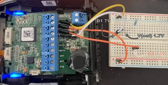
However, upon implementing this voltage divider and connecting it to the microcontroller's pins D0 and D1, I noticed some unexpected behavior. The output voltage across the divider doesn't appear to be around 3.3 V as anticipated. Instead, I'm measuring approximately 1.75 V. Furthermore, the voltage coming from the reader that is connected to the input side of the voltage divider, which should be 12 V, has also changed. It's now reading around 7 V.

enter image description here

Edit: As Justme stated, my reader (ARC-A from STid) probably has an open-collector output. I'm measuring 12 V on D0 and D1. There are 10 kΩ internal pull-ups between D0, D1, and Vin.

When I recalculate my divider after changing the R1 value to 20 kΩ (10 kΩ internal pull-up + my 10 kΩ resistor), instead of 10 kΩ, I find that my voltage divider should output 1.7V. This explains why I didn't get my desired 3.3V.
Sandra
  • 187
  • 7

2 Answers2

4

Well, it turns out that I needed to increase my resistor values by a factor of 10. The 1.2 mA of current sinking through the 10 kΩ resistor was enough to cause my Wiegand line to drop. I wasn't expecting that.

Edit: My assumption about why the voltage collapsed with 1.2 mA of current was incorrect. The reason why my voltage divider wasn't outputting the correct voltage was due to the presence of a pre-configured internal pull-up on the reader. I've updated my original post.

Sandra
  • 187
  • 7
  • Nice! Wouldn't have expected that either, glad that it's now on the internet, so that future searchers stand a fair chance. – Marcus Müller Aug 20 '23 at 12:49
  • @Marcus Müller I was mistaken about my initial assumption. I've updated my post regarding this. – Sandra Aug 21 '23 at 09:26
4

Wiegand readers and similar devices usually have open-collector output because multiple devices can be paralleled with one set of wires to a controller box.

It means that they can only pull the wire low, and there are only weak pull-up resistors in the controller box for all the readers.

So if you add any pull-down resistor load that pulls current to ground, the idle voltage on the wire will drop as it forms a resistor divider with the pull-up in the controller box.

Justme
  • 147,557
  • 4
  • 113
  • 291
  • There was an open-collector, although that wasn't the full story. I've updated my post. – Sandra Aug 21 '23 at 14:16
  • @Sandra I don't get it. The reader having a open-collector output with internal pull-up and your resistors pulling down was the full story like I said, or is there something more to it? – Justme Aug 21 '23 at 14:22
  • Sorry if I wasn't clear on my previous comment. After reading your post, I understood that my reader has open-collector outputs. But you didn't seem to imply the presence of internal pull-ups already present on the reader. Your post talked about weak pull-up resistors on the controller box. This model of the reader includes the pull-ups inside the microcontroller of the reader itself and can only be configured using proprietary software (SECard). I hope this clarifies my previous comment. – Sandra Aug 30 '23 at 10:25
  • @Sandra OK, sorry if I was unclear, but the fact that it did pull the wires weakly to 12V already means it had pull-up resistors so I didn't think properly. Yes the control box might be the only place but it does not have to be. It might have the strongest pull-ups and other devices may have weaker or not at all. They have to be somewhere if a line is weakly pulled up. On a real bus there may be pull-ups on all devices. Depends on manufacturer, as there is no rigidly defined standard, you buy the whole system from a single vendor. – Justme Aug 30 '23 at 11:27