6

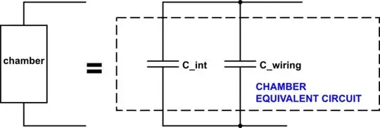
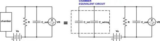
I'm delving into the topic of ionization chambers, but as someone without a background in electrical engineering, I'm finding the equivalent circuits a bit challenging to comprehend. Specifically, I'm puzzled by the placement of the chamber's capacitance in the equivalent circuit. I thought if the capacitor symbolizes the ion chamber's capacitance, it should be on the left of the voltage generator. But in the picture, it's on the right. Why is it positioned like that?

enter image description here

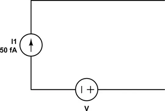
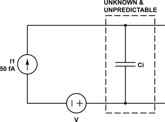
another image, in which \$V_{ch}\$ is the voltage across the chamber, is the following

enter image description here

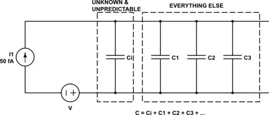
Source of the pictures is the book Glenn F. Knoll-Radiation Detection and Measurement

Tim Williams
  • 33,670
  • 2
  • 22
  • 95
SimoBartz
  • 163
  • 5

4 Answers4

4

The voltage source is a supernode, meaning it doesn't matter which side certain components are connected to it. Capacitors and ideal current sources are such components.

Put another way: consider a change in voltage at the terminals. What current flows? Move the capacitor to the left side. What current flows? Results are identical, therefore the circuits are equivalent.

Illustrating the capacitor here, with dotted lines, I think is intended to remind the reader that chamber capacitance is effectively here and so will affect output bandwidth, independent of the load resistance connected (indeed, inversely proportional to be exact, thus trading off with sensitivity).

Tim Williams
  • 33,670
  • 2
  • 22
  • 95
  • 1
    Agreed. Its a series circuit with DC bias, whose internal capacitance is assumed infinite. so chamber capacitance is effectively in parallel with electronic load capacitance. For pulses, you want to minimize both chamber capacitance and load capacitance in an effort to maximize tiny pulse voltage amplitude. No ground in this circuit is shown - where would you put it? – glen_geek Aug 15 '23 at 13:31
  • I don't understand you answer, can you say it in a simpler way? maybe you could draw a circuit to be more clear. Also, I added another image that may help the understanding of the situation. Note that there are three different answers here, so I'm now more confuse than before – SimoBartz Aug 15 '23 at 13:39
  • It's a concept from introductory electronics/physics. Perhaps this will be illuminating? https://electronics.stackexchange.com/a/497427/311631 – Tim Williams Aug 15 '23 at 13:44
  • As this is a beginner subject, I would urge a beginner's solution: rather than giving the answer away (in fairness, I already have; but since there are further questions--), hint in the direction to pursue further study. If you are completely new to circuit analysis, you will find this term in the topic of nodal analysis, which is well worth studying; if you have some physics or math background, the approach should be easy enough (systems of linear equations), and what's most important is seeing how to translate between schematic and equations. – Tim Williams Aug 15 '23 at 13:47
  • @TimWilliams thanks for the advice, but before moving on and studying a new subject, are you sure to be right? because in the second image that I added the chamber voltage is not across the capacitor C. Also, a simple simulation of the circuit shows that there is a difference in putting the capacitor on the left or on the right side: https://www.falstad.com/circuit/circuitjs.html?ctz=CQAgjCAMB0l3BWcMBMcUHYMGZIA4UA2ATmIxEPKQUhAQFMBaMMAKAHcQAWMQkFPHjpcu-QVFYBLbrzFCefEUNox4bAG7DRSkBkjauyqN1pIVUaAlYBjLXLs6VsNd2h5iKAVyIJs2Lhh4EKqQbABOIEF8AkJR3IbGYPAcuvr2cTESnHoGsbKOKQrxQggixVl2mTn2kKxAA – SimoBartz Aug 15 '23 at 13:52
  • The only difference is whether to add or subtract $V_0$ from $V_{ch}$; the dynamics (change in voltage and current over time) are identical. Note that we cannot reduce $V_{ch}$ itself, because it is a nonlinear device (clearing charges before they recombine, or avalanche multiplication, depends on bias voltage) so it violates superposition and must be expressed in its own terms. The surrounding circuit obeys superposition and $V_0$ can be moved around as needed. – Tim Williams Aug 15 '23 at 13:56
  • I disagree, the voltage difference between the capacitor C is small, while between the chamber electrodes is small. If you put che capacitors left or right things change. Also, I'm not totally new to these things, I just said I'm not an expert – SimoBartz Aug 15 '23 at 16:07
  • A capacitance obeys the equation $I = C \frac{dV}{dt}$; its behavior depends only on the rate of change of V, not its absolute value. For a mechanical analogy, a 1kg mass is still 1kg whether it's resting on the ground or flying through the air; $F = m \frac{dv}{dt}$ does not depend on the absolute velocity, only its rate of change (acceleration). – Tim Williams Aug 15 '23 at 16:10
  • the absolute value of V is important for the ionization chamber, it prevent recombination of electron and ions – SimoBartz Aug 15 '23 at 17:34
  • Correct; I already noted that. – Tim Williams Aug 15 '23 at 17:35
4

The illustrations are misleading. The ionizing chamber is already drawn using the capacitor symbol and has a presumed capacitance. The additional C on the right side of the Vo source could only add parasitics outside of the chamber.

And you're right, if the chamber was drawn to look not like a capacitor, then the equivalent elements should be right next to it - on the left side of the picture, just to communicate things well.

As others have mentioned, the circuits are equivalent no matter whether the C is on the left or right side of Vo. But the purpose of the illustration is to communicate ideas, not to be "clever" and obfuscate the purpose of the illustration.

If I were drawing the thing, I'd draw the ion chamber as a "black box" - a two-terminal device, with equivalent devices shown explicitly:

schematic

simulate this circuit – Schematic created using CircuitLab

IMHO, the diagram below would do a much better job at communicating the central idea here:

schematic

simulate this circuit

3

Ionisation chamber shown in your image is not a capacitor or can't be modelled as a capacitor/capacitance. It can be modelled as a current source instead.

schematic

simulate this circuit – Schematic created using CircuitLab

But, as every other practical electrical components, it exhibits a parallel capacitance, \$C_i\$, which is a part of the chamber:

schematic

simulate this circuit

So the capacitance \$C\$ in the image represents that parallel capacitance, \$Ci\$, plus everything else (wires, components, measuring devices, etc):

schematic

simulate this circuit

Rohat Kılıç
  • 33,940
  • 3
  • 29
  • 85
  • thanks for your useful answer, it helps. However, I still don't understand why the capacitance Ci is on the right of the capacitor. I edited the question and added another picture, maybe it can help – SimoBartz Aug 15 '23 at 12:23
  • I tried to simulate the circuit that you draw in the case the current is zero, and it seems that the capacitor voltage is zero too, that is incorrect. However, I'm aware that I don't know this subject well, any explanation will be very useful.

    Circuit: https://www.falstad.com/circuit/circuitjs.html?ctz=CQAgjCAMB0l3BWcMBMcUHYMGZIA4UA2ATmIxAUgoqoQFMBaMMAKAHcQAWMQkFPPCAyROfAVBYBLLjy6dB3Xv0FVILAG4zeneUJFyVULrSOroCFgGM9onYOGjlp2PAhm4rIA

    – SimoBartz Aug 15 '23 at 12:42
2

I thought if the capacitor symbolizes the ion chamber's capacitance, it should be on the left of the voltage generator.

The large capacitor on the left is representing the capacitance of the ionization chamber.

But in the picture, it's on the right. Why is it positioned like that? Here C represents the capacitance of the chamber plus any parallel capacitance

The capacitor on the right is representing the parasitic capacitance of cables/connections etc.. Hence why we show it with dotted lines. This implies an unpredictable value.

It needs to be taken into account when measuring pulses across the resistor and, is shown in your diagram as a reminder.

Andy aka
  • 456,226
  • 28
  • 367
  • 807
  • thanks for your answer, unfortunately the book specify that the one on the right represents the capacitance of the chamber plus any parallel capacitance. I modified the picture to show the legend of the picture. This scheme is used many times in the book. It seems to me that the ion chamber picture is not even an electrical component in the picture, I don't know, I need help – SimoBartz Aug 15 '23 at 09:48
  • sorry, it is possible that your answer is correct and that I'm misunderstanding the picture. If that is the case, can you explain better the convention that the author is using? it would be very useful – SimoBartz Aug 15 '23 at 10:44
  • @SimoBartz the big capacitor on the left is the chamber so, it doesn't need representing as some part of the smaller capacitor on the right. I think the author is mistaken in his use of words. Because of what I see as an error on the authors part it makes no sense to try and explain what convention he is using. I would just be guessing or repeating myself. – Andy aka Aug 15 '23 at 12:11
  • it seems strange because this is the fourth edition of one of the most used book in the topic. Also, there other part in the same book with the same scheme, I added another image to my question, give it a look – SimoBartz Aug 15 '23 at 12:24
  • If it looks like a capacitor and is wired like a capacitor then.... – Andy aka Aug 15 '23 at 13:07
  • I found another picture in which the chamber voltage seems different respect to the voltage across the capacitor C, maybe you are right, I don't understand – SimoBartz Aug 15 '23 at 13:36
  • note that there ate three different answers for this question, I'm now more confuse than before – SimoBartz Aug 15 '23 at 13:42