4

I have an existing automotive circuit simplified in the image. The loads (2 or more solenoids in parallel) share a 12V supply and are individually switched to ground through the car's ECU.

I need to detect when any one of the circuits close (only one closes at any one time), using a single PIC digital in (or comparator if I must), and with the minimum of wiring (the car's wiring is buried and a pain to get to although the common 12V rail is easy to get to). I can't disturb the ground plane(s) and can't add much load.

I have looked at highside current sense ICs but can't find them in DIP and don't want to use SOT if I can help it as I will be hand-soldering to stripboard. Anyway, I don't need to know how much current is flowing, just whether it is or not.

There must be a simpler solution that I'm missing?

two loads in parallel

Jon
  • 725
  • 2
  • 8
  • 17

5 Answers5

3

Here is a simple solution:

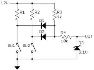
R1, R2, SW1, and SW2 represent the circuit in the car that you can't modify. D1 and D2 perform a OR function so that the bottom end of R3 goes low when either or both switches are closed. I would put D1, D2, and R3 close to where these switches are, then R4 by the PIC.

You have to assume the long line will pick up noise and transients, so R4 provides some impedance for D3 to work against to clamp the signal at the PIC to safe levels.

Added:

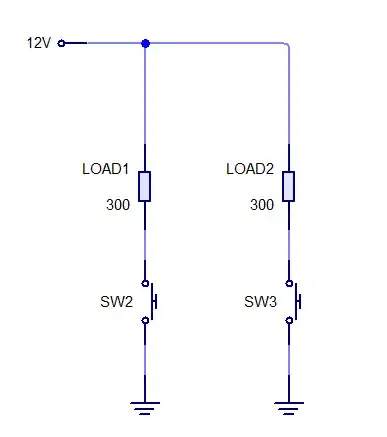
There is confusion as to whether or not you can get at the low sides of the loads. My first reaction was that this would be the easy way to connect because you only have to monitor the voltage. It therefore doesn't require breaking any connections, just tapping off existing connection points.

However, if it is really better to break into the high side power connection to the loads for some reason, then here is a simple way:

Again, R1, R2, SW1, and SW2 are the switches and loads that you presumably can't get into. This requires breaking the power connection to the loads and inserting R3, R4, and Q1. R3 is a current sense resistor sized to produce enough of a voltage drop to turn on Q1 when either of the loads is on. R4 is just to limit current thru the base of Q1 to safe levels.

The long wire to the PIC board is intended to be between the collector of Q1 and the top of R5. With the R5, R6, and Q2 receiving circuit, a lot of noise and nasty spikes can be tolerated on that line. When Q1 is on, Q2 will be driven on, which will drive OUT low. Th collector of Q2 goes directly to a PIC pin with a internal pullup. Noise shouldn't be much of a issue here since R5, R6, and Q2 are intended to be on the same board close to the PIC.

Overall, when a load is turned on, the PIC input will go low.

Olin Lathrop
  • 313,258
  • 36
  • 434
  • 925
  • I like this but my only reservation is the additional connections to each load. It is certainly my favourite if I can't work the opto solution. – Jon Apr 29 '13 at 12:25
  • @Jon -- Wait a minute! You just told us (me) that you can't access the low side of the load. – DrFriedParts Apr 29 '13 at 14:51
  • @DrFried: He said in a comment to the question that he can't get to the low sides of the switches, not the loads. – Olin Lathrop Apr 29 '13 at 14:56
  • Yeah, that's what I thought. I was questioning his understanding, not yours. His comment on my answer is wrong... or at least confused. – DrFriedParts Apr 29 '13 at 15:00
  • It's me that's confused as I didn't notice the zener (or didn't pay enough attention more like... – Jon Apr 29 '13 at 15:24
  • Sorry...this has taken me a while to get the relevant components and try it out. This works perfectly! Mental note to play with PNPs a bit more and get familiar! – Jon May 07 '13 at 09:25
1

If you can access the 12V side and, all you care about is any one-contact (or more) closing then possibly an opto coupler may work (although it will "lose" something like 3V including current limiting and diodes across the LED to protect the opto-diode from being over-stressed when more contacts close).

The opto-coupler output will be a transistor that, with the appropriate pull-up resistor on the collector, will provide an input to your monitoring device.

Andy aka
  • 456,226
  • 28
  • 367
  • 807
  • I like this. The loads are solenoids so I can probably deal with a volt or two drop, but need the current. I have simulated it with a small resistor for the LED side of the opto and a second small resistor in parallel to reduce the current through the opto, and nothing blows up. I wonder if this would work? – Jon Apr 29 '13 at 12:30
1

You can use the Analog Devices AD626 single supply Differential Amplifier available in a DIP-8 package ($8.62 in single units at Digikey) for high side current sensing.

The AD626 can handle 24 Volts common mode input if powered by 5 Volts, or 6 x (Vcc -1) per the supply voltage. In case your device uses a 3.3 Volt supply rail, the CMR is +13.8 Volts, which may be somewhat borderline with a 12 Volt automobile circuit.

As the part has a maximum gain of 100, a very small value shunt resistor would suffice to sense presence / absence of current: If expected maximum current is in the 0.5 Ampere range, then a 0.1 Ohm shunt resistor would provide a full-scale (5 Volts) output.

If expected current is significantly higher, then either a lower shunt resistance (thus lower heating issues) or reducing the gain to 10x would be preferable.

The linked datasheet provides a current sense schematic for the application:

Schematic

Notes:

  • For sensing the two paths individually, two of these diff-amps would be needed, and these are not inexpensive parts.
  • Allowing for significant headroom in the output signal is suggested: As the purpose is solely to detect current flow, not to measure it, a small designed voltage level for the output would allow this headroom.
  • As other answers have pointed out, in an automotive environment, overvoltage clamping, fast flyback diodes and other precautions are a necessity.
Anindo Ghosh
  • 50,446
  • 8
  • 105
  • 201
0

The Voltage Divider

If you are looking for a simple solution above all else, you could just add two resistors, but they'll have to be very large:

schematic

simulate this circuit – Schematic created using CircuitLab

This will produce 2.8V at the MCU input (e.g. designed for a 3V logic) when the switch is open and 0.0V when the switch is closed.

Please Note:

  • It will add about 1uA each (2uA total) continuous leakage to the system. That should stay below the 10uA guideline I see typically used in automotive applications.
  • You should add a clamping diode if the load is inductive (relay, solenoid)
  • You should add a series resistor to the MCU input path to protect against the general automotive environment (voltage spikes)

Hopefully, adding four passives isn't too bad...

DrFriedParts
  • 12,562
  • 37
  • 54
  • sorry, I will edit my question to be clearer that those switches are not real, they are internal to the car's ECU and I am unable to get to the lowsides. – Jon Apr 29 '13 at 11:14
  • So what can you get to? Just the high side of the LOADn resistors? – DrFriedParts Apr 29 '13 at 11:16
  • The high side of the loads is easy. The low sides are separate wires into the ECU and are not easy but possible. I'd rather avoid connecting to each load separately. – Jon Apr 29 '13 at 11:20
  • Your only option at that point is to splice small sense resistors into the lines and use a high-side current-sense amplifier. You haven't given us anything else to work with... although it's probably easier to open up the ECU and implement what I suggested above, since the ECU is behind a connector (and therefore removable). – DrFriedParts Apr 29 '13 at 11:29
  • Unfortunately getting into the ECU isn't an option in this case as the circuit is to be an add-on for fitting by the end user. I was hoping there would be something simpler to implement but if a current sense amp is the only way forward I'll have to look into the options. My biggest problem there is that I can't seem to find a highside current-sense package I can easily use with 0.1" stripboard. – Jon Apr 29 '13 at 12:08
  • Is 3M/10M resistor not a bit much in an automotive application? Seems pretty sensitive to my for noise. – jippie Apr 29 '13 at 14:19
  • @Jippie -- Yeah, that's definitely a concern. I'd do some low-pass filtering in software. You'll have to debounce it anyway. – DrFriedParts Apr 29 '13 at 14:49
0

If you have physical access to the solenoids, you could mount a hall effect sensor to detect the magnetic field generated when the solenoid is energized. This would require 1 sensor per solenoid, but it would be completely non-invasive, from the standpoint of splicing into existing wiring.

jwygralak67
  • 709
  • 4
  • 9