0

This is my first post here, I've been a reader of this forum for a while.

I've been analysing this problem for hours and still can't find a way to solve it, I would really appreciate your input. Thank you for your time.

PD: I'm not an expert in electronics so, sorry if it's a super simple problem.

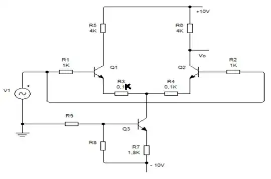
Data given for the problem:$$re_3=10.5\Omega ,ro_3=50k \Omega ,\beta = 80$$

Find: $$Av=?,R_9=?, V_1=15mVpp$$

enter image description here

From MSc. Junior Rodríguez, professor at URBE University in Venezuela.

For voltage gain: \$Av=\frac{V_o}{V_i}\$.Using \$V_o\$ from \$Q_3\$.

For current in collector Q3: \$re_3=\frac{26mV}{I_{E3}}\$. The problem is that despite I find the voltage in R8 and R9 there is not a viable way to solve this problem, because if I use a voltage divider in \$Q_3\$ I won't have a numerical response for \$Vbb_3\$. Same way with any analysis involving those two resistors without any value, I would like to know how to calculate them (if possible of course). Thanks in advance.
  • You need to solve for resistances 8 and 9 – Luis González May 28 '23 at 21:27
  • Sorry if I make mistakes writing in English, it's not my native language. I might have some grammatical errors. – Luis González May 28 '23 at 21:30
  • I've tried all DC analysis but I always have 2 unknown variables, I tried AC analysis but the same I always have 2 unknown variables, for example in AC using the re_3 data, I still have R8 and R9 as unknown varibles, same way when I try to use voltage divider in Q3. With $$re_3=26mV/I_{E3}$$, I find Ie_3 but the real problem I have is to find the current flowing on R8 and R9. I do have: voltage r8=5.16V and voltage r9=4.84V. – Luis González May 28 '23 at 21:42
  • Only the ratio of R8 and R9 is important - their absolute values could be anything over a wide range. – Kevin White May 28 '23 at 22:13
  • @KevinWhite could you please explain it better? Do you mean for example state that R8 is 1/3 of R9? – Luis González May 28 '23 at 22:21
  • @LuisGonzález Is R3 really 0.1 and R4 really 0.1k? And since you are given $r_e^{:'}$ for $Q_3$ you don't really need information on R8 and R9. They are whatever is needed to make that operating point true. – periblepsis May 28 '23 at 23:07
  • @periblepsis it is an error of design, in fact both R3 and R4 are 0.1k, thank you for your response. Honestly, I thought about giving R9 any value to make that operating point true, but my teacher says R9 can be calculated, just that he doesn't want (or know) to give the answer. I appreciate your input and let me know if you have another analysis in mind. – Luis González May 29 '23 at 00:12
  • What does "Av" mean? – MikroPower May 29 '23 at 00:33
  • @MikroPower Av means voltage gain using Vo in Q2, $$ Av=\frac{V_o}{V_i} $$ – Luis González May 29 '23 at 00:37
  • @LuisGonzález - Yes, all that is important is the voltage at the base of Q3. That is determined by the ratio of R8 and R9 (and to a small extent the base current of Q3). Their absolute values only have a secondary effect: If they are too high the base current for Q3 will have a significant effect, if they are too low their power consumption will be unnecessarily high. Normally resistors in the range of 1k to 10k would be used for something like this where the absolute value is not critical. – Kevin White May 29 '23 at 00:59
  • @KevinWhite great! thank you for your answer Kevin. – Luis González May 29 '23 at 01:36
  • @LuisGonzález Given the schematic I believe I'm seeing, you are supposed to analyze the CMRR (hopefully, very low voltage gain for both inputs moving together as shown in the diagram.) This highly depends upon the current sink impedance. Is that what you feel you are being asked to yield, as well? (See, for example, this post at EESE.) – periblepsis May 29 '23 at 11:31
  • @periblepsis Oh, I didn't see the edit. Thank you. – Luis González May 29 '23 at 11:38
  • @LuisGonzález The link I provided already provides some pretty solid 'guidance'. Do you agree that this is a CMRR question? Not a differential gain question? (Long tailed pairs have both common mode and differential mode gain.) – periblepsis May 29 '23 at 11:40
  • @LuisGonzález You have no information on the R8/R9 divider. No way to work out its stiffness. So all you really have is an Early Voltage of about 100 to 125 V for Q3. (There is also a Late Voltage and various other details in the models, but no info on any of that here.) So the change in the tail current, at the operating point indicated, can be pretty readily worked given the limited info to work with. – periblepsis May 29 '23 at 11:49
  • @periblepsis It is not stated, but given that I have to find Av and it is not defined if it's common mode or differential mode, now everything makes sense. Maybe it's referring to fing both Av and find CMRR. Because (at least the formula the professor gave us) $CMRR=\frac{Av_d}{Av_{cm}}$ where $Av_d$ is differential gain and $Av_{cm}$ is common mode gain – Luis González May 29 '23 at 11:51
  • @LuisGonzález Just look at V1. It's single ended output is driving both sides at once. That's "common mode". As I see it, anyway. Changes will lift or sink the emitter voltage on both Q1 and Q2, together. These will impact the tail current (Q3 collector current) because of the Early Effect (all you have to work with, right now.) That impact will be seen at Vo. That's discounting secondary effects on Q1 and Q2, about which you've been given nothing much. Which is yet another reason I think this is about CMRR due to Q3 only, treating Q1 and Q2 as more ideal. But what do I know? – periblepsis May 29 '23 at 11:52

0 Answers0