I redrew the circuit and tried very hard. But nothing makes sense. I cannot just figure out how I should approach and analyse this circuit. This is as far as I have reached.

I redrew the circuit and tried very hard. But nothing makes sense. I cannot just figure out how I should approach and analyse this circuit. This is as far as I have reached.
This question is going to be closed, no doubt. Before it stops accepting answers, let me give you some hints, which I strongly recommend you study.
Redraw the circuit with component designators, so people don't have to say things like "the 2kΩ resistor at the top left. Label it "R1", for example. Label everything.
Note that in your redrawn circuit, the current source points the wrong way. This will be viewed by the community here as inattention to detail, or even just lazy. Check your work.
In the following circuit, what is the relationship between potentials \$V_A\$ and \$V_B\$, at nodes A and B? Why? Don't assume there's anything else connected, all there is is what's shown:
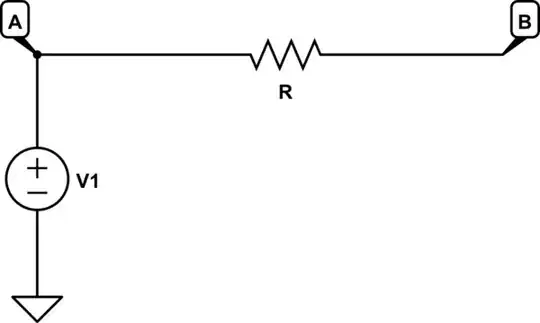
simulate this circuit – Schematic created using CircuitLab
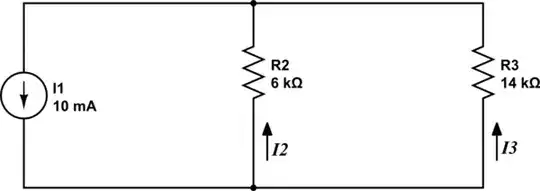
In the circuit below, what's the relationship between \$I_2\$ and \$I_3\$? Why? What are their values? Again, there's nothing else connected, all the information you need is right there:
These examples are relevant to your original question, and may be considered hints. The next thing you should do, before asking again, is figure out how they are relevant.
If you have problems answering these questions, then you seriously need to study Ohm's law, and Kirchhoff's voltage and current laws again. They are the only things you need to apply here, to answer my questions.
Since you've found the voltage across the two vertical-pair paths, presumably you are able to apply Ohm's law to find the current through them.
They will be:
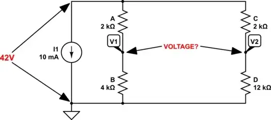
$$ \begin{aligned} I_2 &= \frac{42V}{6k\Omega} = 7mA \\ \\ I_3 &= \frac{42V}{14k\Omega} = 3mA \\ \\ \end{aligned} $$
You can now apply Ohm's law again to find the voltages across all the resistors.
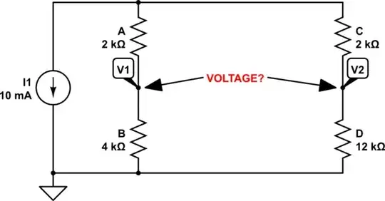
Your original drawing/schematic:
 The same schematic in our schematic editor:
simulate this circuit – Schematic created using CircuitLab
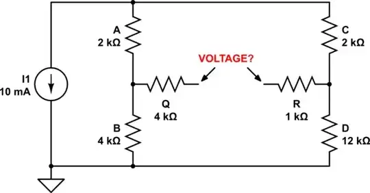
The FIRST thing to do is ignore and remove the resistors Q and R, since there is no voltage drop across them without a load:
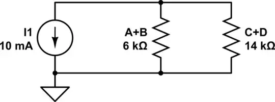
Now you add resistances in each series string:
From here, you can:
Let's use the first method for now by first getting the total parallel resistance of both strings:
(6k x 14k) / (6k + 14k) = 84k / 20k = 4.2k
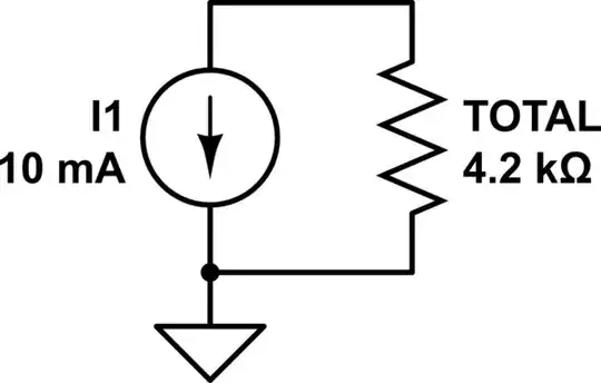
Now we get the voltage across the current source and both of the series strings by simply multiplying the current source current with the total resistance:
10mA x 4.2k = 42V
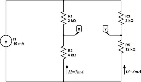
Then we apply this calculated voltage to our original schematic:
Now we have 2 ways to figure out voltages across the individual resistors:
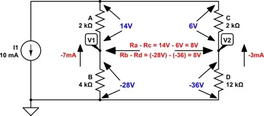
Now you take the difference between the V1 and V2 by using either the upper or the lower resistor voltages:
Ra - Rc = 14 - 6 = 8V
Rb - Rd = -28 - (-36) = 8V
So 8V is the voltage between the two points, and its polarity will be the same whether you use the difference between the lower or the upper resistor voltages.
This is because if you use the lower side of the current source as GND or 0V reference, you will get negative voltages, -28V for V1 and -36V for V2; V1 will be by 8V more positive than V2.
If you use the upper side of the current source as GND or 0V reference, V1 across Ra will be +14V and V2 across Rc will be +6V, again making V1 by 8V more positive than V2.
OLD ANSWER (without schematics):
You have made some correct steps, but then you got confused as to how does the voltage appear and manifest across the given resistors.
The first thing to do is ignore or remove the resistors Q and R, since they have no effect on the output voltage without a load.
Then you use one of the 2 ways to solve this circuit:
Method 1.
a) You figure out the total resistance across the current source to get the voltage across it.
b) You then calculate the potentials you have marked V1 and V2 in your next step - I have marked them Q and R.
You can calculate them as a ratio of a single resistor resistance to the total string resistance - B/(A+B) - and then multiply that ratio (4/6 or 2/3) with the voltage across both A and B (42V). Then you do the same for the other side/string (C and D, using the voltage across D).
Or you can get those voltages/potentials by calculating the currents through each series string (AB and CD), and then multiply those currents with the lower (you could use either the upper resistors (A and C) or lower resistors (B and D) for calculations; the resulting difference or the voltage between Q and R will be the same.
c) Calculate the difference between the Q and R or V1 and V2 points. That's your output voltage.
Method 2.
a) Calculate the resistances of each series string, A+B and C+D, which will be 6k and 14k.
b) Calculate the current through each series string by the ratio of the string resistances to get the ratio of currents through them:
14k / 6k = 2.333
Since the CD string has 14k or 2.333 times the resistance of the AB string (6k), that means that the current through it will be 2.333 times lower than through AB, or that the AB current will be 2.333 times higher than the CD current.
This can be represented as 10mA / (2.333+1) = 10/3.333 = 3mA
3.333 is the total ratio factor by which we divide the total current to get the current "unit" of 3mA.
So, 3mA is the current through the CD ctring (14k), and 2.333x3mA = 6.999mA or 7mA is the AB string current.
c) Now you calculate the voltage across the upper resistors, A and C (again, you can also use the lower resistors):
2k x 7mA = 14V; 2k x 3mA = 6V
d) Finally, you calculate the difference between the two upper (or lower) resistors to get the voltage between V1 and V2:
14v - 6V = 8V
And there is your voltage.
It may help to have yet-another-perspective (my YAP on it.)
Here's your schematic with some added notes and thoughts:

I chose to ground one side of your \$V_{_\text{O}}\$ for convenience's sake. This means that whatever I work out for the voltage at \$V_3\$ will be the Thevenin voltage between the two nodes shown for \$V_{_\text{O}}\$ (with no injected test current.) I could have made a different choice. But this one seemed "better" to me.
I also labeled your current source and my added test current that will be used to work out the Thevenin impedance. The test current will be zero, to start (so as not to affect the node voltages.) The test current will then be made to be one (\$1\:\text{A}\$) to see what happens to \$V_3\$'s voltage. That will tell us the Thevenin impedance that must be present there. Once that is done, the values of \$R_{_\text{Q}}\$ and \$R_{_\text{R}}\$ can be added to that, since they are in series with the Thevenin impedance computed without them.
Using nodal analysis, you can form three equations:
$$\begin{align*} \frac{V_1-0\:\text{V}}{R_{_\text{A}}}+\frac{V_1-V_3}{R_{_\text{C}}}+I_1&=0\:\text{A} \\\\ \frac{V_2-0\:\text{V}}{R_{_\text{B}}}+\frac{V_2-V_3}{R_{_\text{D}}}&=I_1 \\\\ \frac{V_3-V_1}{R_{_\text{C}}}+\frac{V_3-V_2}{R_{_\text{D}}}&=I_0 \end{align*}$$
Setting things up this way, I can make \$I_0\$ either \$0\:\text{A}\$ or \$1\:\text{A}\$ to see how the voltage at \$V_3\$ changes. And from that, work out the Thevenin impedance. (The Thevenin voltage is achieved already by examining \$V_3\$ when \$I_0=0\:\text{A}\$.)
Solve those equations, simultaneously, and then solve for two cases: \$I_0=0\:\text{A}\$ and \$I_0=1\:\text{A}\$. The Thevenin result will be \$V_{_\text{TH}}=V_{3}^{I_0=0\:\text{A}}\$ and \$R_{_\text{TH}}=\frac{V_{3}^{I_0=1\:\text{A}}\,-\,V_{3}^{I_0=0\:\text{A}}}{\left(I_0=1\:\text{A}\right)\,-\,\left(I_0=0\:\text{A}\right)}+R_{_\text{Q}}+R_{_\text{R}}\$.
There are graphical ways, as well.