You write that "current in loop1 say i1 such that direction in 2 ohm resistor is same in both loops". I don't like using number subscripts for the current loops because you already have existing currents with number subscripts. So to avoid any of that kind of confusion I've used \$x\$ and \$y\$ as subscripts for the loop currents:
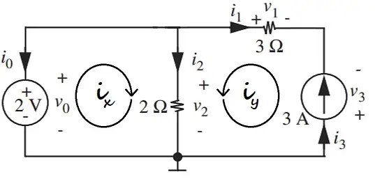
Just to put it on top of the table and in plain view: It does not matter which directions are picked for the mesh current loop directions. One must simply be consistent in their application, once chosen.
I like to follow the direction indicated by the arrow of each loop, because I'm a cooperative type and don't like to be seen as always going against the grain. And I'll start at the grounded node in each case because I'm ground-biased. What can I say? (These choices are also arbitrary.)
$$\begin{align*}
0\:\text{V}+2\:\text{V}-2\:\Omega\cdot\left(i_x+i_y\right)&=0\:\text{V}
\\\\
0\:\text{V}-v_{_3}-3\:\Omega\cdot i_y-2\:\Omega\cdot\left(i_x+i_y\right)&=0
\:\text{V}
\\\\
i_y&=3\:\text{A}
\end{align*}$$
The last equation isn't a mesh loop equation but a statement that says \$i_y\$ is in the same direction as the current source and that it must also take on the exact value of the current source. This sets up three equations in three unknowns. (Well, technically, one of them is already known: see last equation.)
The value could replace the use of \$i_y\$ in the loop equations, instead:
$$\begin{align*}
0\:\text{V}+2\:\text{V}-2\:\Omega\cdot\left(i_x+3\:\text{A}\right)&=0\:\text{V}
\\\\
0\:\text{V}-v_{_3}-3\:\Omega\cdot 3\:\text{A}-2\:\Omega\cdot\left(i_x+3\:\text{A}\right)&=0
\:\text{V}
\end{align*}$$
That sets up two equations in two unknowns.
Either way, solvable. Solved, the values for all the other unspecified values can be achieved. (Don't forget that from direct inspection \$i_{_2}=i_x+i_y\$, for example.)
Another way to look at it is that you already know what voltage difference is across the \$2\:\Omega\$ resistor. So you know what the net current in it must be. The difference between this and the current source must be what is happening with the current through the voltage source. It all has to balance out.

