I have an HDMI Matrix switch, cable boxes and DVR in a central cabinet that services all of the TVs in my home. The matrix switch allows the sharing of the cable boxes and DVR between all of the TVs. The matrix has IR input and output ports for each HDMI channel that will route the IR input signals to the appropriate IR output based on the which input is selected for each output. This will allow each TV to have an IR receiver back to the matrix to switch channels on the cable box or DVR control. Since the distances from the TVs to the central cabinet are on the order of 100 ft., I have had to use 12VDC powered IR blasters for each TV to get the IR signal back to the matrix. Each blaster has an IR emitter output, but the matrix is looking for an IR receiver output.
I have overcome this issue by taping an IR emitter to an IR receiver; plugging the emitter into the IR blaster and the IR receiver into the matrix. This works, but you have to adjust the distance and aim between the emitter and receiver taped back to back to get reliable control. I do this by using a small piece of 1/2" PVC pipe with the emitter and receiver taped to each end of the pipe and adjust the length as necessary.
I would like a more consistent and reliable connection in lieu of the back to back IR emitter and receiver cable solution. I have tried to apply a 6N136 opto coupler as an equal to the back to back. I selected this chip as the output is an "IR transistor" and expected it to be generally identical to the IR receiver cables that I was using.
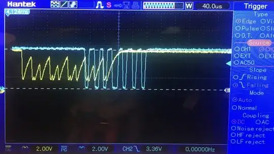
The output of the IR receiver cable produces a 0-5V square wave pulse train at 38KHz as expected as the receiver does not demodulate the signal received from the transmitter/remote control.
The IR blasters/boosters being used have 6 emitter outputs, so I am able to drive my back to back cable and a 6N136 in parallel and compare the outputs. Transmitting from an IR remote control into the blaster receiver, the attached oscope screenshot it can be seen that the back to back output (blue trace) has the typical 38KHz pulse train, while the output of the 6N136 (yellow trace) obviously needs more output circuitry than a typical 1K ohm pull up resistor to get a comparable output to the receiver output of the back to back cable setup. I guessed wrong that the IR receiver cables that you purchase online are just IR receiver transistors. There must be additional circuitry to get the square wave pulse train.
Is there anyone out there that has any idea what additional circuitry is needed on the output of the 6N136 to get the signal to look like the output from the back to back IR cable setup?
Overall schematic below.
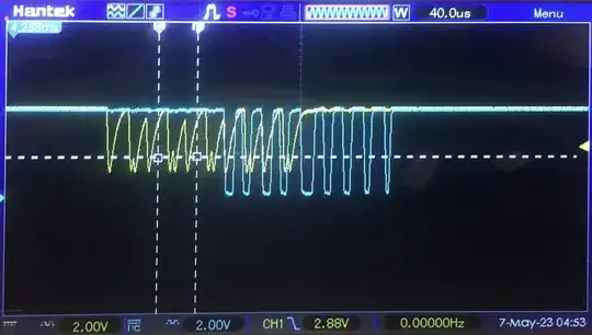
I added additional emitters to the blaster output ports just by trial and error and note that the output from the 6N136 Vpp increased and the "high" output reached the supply voltage level. This leads me to believe that the input signal to the 6N136 will need additional study. See screenshot below. This gets closer to the output of the "back to back" (actually "face to face" ;) ) IR emitter/receiver output. Further investigation seems to indicate that a comparator must be included in the IR receiver cable to get the "near" square wave output.
6N136 output with multiple IR emitter cables connected (multiple IR emitters must change the voltage/current to each emitter generated by the blaster.
Nedd-
Yes, the output of the blaster is 12V. The blaster is used not for multiple ir emitter outputs, but to get the received ir signal at the TV back to the matrix. A "typical" 5V ir receiver (the ones supplied with the matrix) will not get the signal back, it is too far. The 12V receiver and blaster is designed for a remote receiver and up to six emitters. Further experimentation has led me to take the 12v receiver from the blaster and wire it directly to 12V and exercise it with a remote control. It does not behave as the 5V receivers, even with various pull up resistors on its signal output, you get nothing close to the typical square wave as the 5V ir receivers produce. Adding pull up resistance does get the signal levels closer to 0 and 12V, but the 'pulse widths' become inconsistent and I expect not within a 38KHz tolerance. I believe this 12V receiver has different output circuitry than a 'typical' 5V receiver and is specifically designed to work with the blaster and directly drive ir emitters. I took the cover off the blaster, it is no more than a resistor in series with each emitter output connection all paralleled with the output from the receiver. I don't think I have any options other than to work with the receiver signal as it is. As I mentioned above, adding more emitters does increase the signal peak to peak which may help when applying a comparator on the 6N136 output. Thanks for your input.
Update:
Further testing has confirmed that the output from the 12V IR receiver even unconnected to the blaster produces the complex shaped wave form as shown above. The upper and lower peaks are not consistent although they repeat and are at 38Khz.(double lower peak counting as a single peak) Whether circuitry is applied at the input or the output of the 6N136 I have no idea what that circuitry would be. It would appear that a complex multi-function circuit would be required to end up with a similar square wave that is output from the back to back 5V emitter/receiver that I was trying to replace. (the blue pulse train) I don't see that a simple comparator is the solution as I hoped initially.


