0

I am undecided whether or not to add a common mode choke in my product that needs to undergo EMC testing for CE marking. Let me describe my case... My device is split into 2 parts, connected with each other with a 2 meter cable. The overview is the following: enter image description here
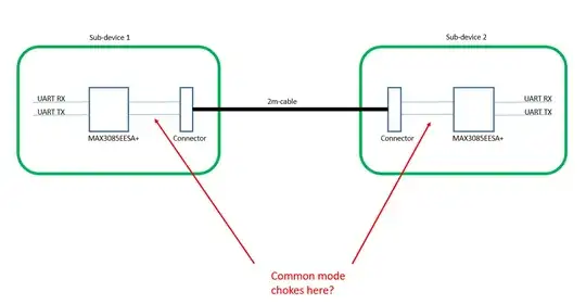
For better comprehension, here the detailed sub device: enter image description here
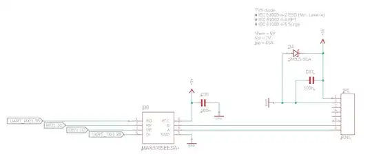
I got different opinions about adding a common mode choke very close to the connector. What's your opinion on this? I do not expect UART frequencies higher than a few kHz. My main goal is to, control the emissions to pass the EMC test.

Thank you:)

Voltage Spike
  • 82,181
  • 41
  • 84
  • 220
mdir
  • 115
  • 4
  • In the EMC test, they inject the signals into your cables. It does not matter how long your cables are. Depending on the test, a specific amount of noise will be injected into the cables. I'm gonna say go with the filters. Unless you know the EMC test signal levels and they are very low that does not affect your communication (very unlikely). – Saadat May 04 '23 at 08:35
  • 1
    @Saadat thank you for your answer. Do they inject noise even if the connectors are not exposed and they are "locked" in the enclosures? – mdir May 04 '23 at 08:42
  • 1
    "needs to undergo EMC testing for CE marking" doesn't mean jack. What is the product, what are the requirements, how high radiated susceptibility tests do you plan for, in which frequency span? Also what are the baudrates, radiated emissions may or may not be a walk in the park... not so much if you are running at speeds past 1Mbit baudrates. – Lundin May 04 '23 at 09:20
  • 1
    @mdir Conducted susceptibility/emissions testing is done on the "DUT" in the form it will used in the real world. They will not open up the enclosure if that's not how the product will be used. So if this is a battery application with no supply cable then conducted tests don't apply. ESD testing will be done similarly, applied to critical points on the enclosure (basically the test engineer will be as evil as possible and look for exposed metal parts like screws, then shoot contact charges there) – Lundin May 04 '23 at 09:22
  • 1
    Just adding a choke doesn't do much. You would also need filtering capacitance. There's also no termination resistance shown. Note that all concerns can be sidestepped by using a shielded cable, and you could remove the RS-485 interface and pass plain logic signals instead. The TVS also doesn't seem necessary. – Tim Williams May 04 '23 at 09:27
  • @Justme No problem:). So, what's your final opinion? – mdir May 04 '23 at 10:16
  • 1
    @TimWilliams "Note that all concerns can be sidestepped by using a shielded cable" Aka hiding your EMC problems under the carpet. Have you ever used shield cables? They are approximately 10 to 100 times more expensive than ordinary ones. "you could remove the RS-485 interface and pass plain logic signals instead" That's plain awful advise, the differential signal is what makes RS-485 rugged. "The TVS also doesn't seem necessary" It is mandatory in pretty much every serious application for use in the real world. Not necessarily on the CAN lines but on the supply. – Lundin May 04 '23 at 11:45
  • @Lundin TIL USB can't exist – Tim Williams May 04 '23 at 13:16
  • @TimWilliams I don't know what "TIL USB" is, did you mean TTL USB? USB is also using differential signals just like RS485 and there as well for very good reasons, since it's such a rugged and proven in use technique. – Lundin May 04 '23 at 13:24
  • "Today I Learned". I shouldn't be so dismissive, but we had an extensive thread on this recently: https://electronics.stackexchange.com/questions/661902/usb-shielding-device-or-host-side/661937#661937 A shielded cable is precisely the reason USB's logic level or lesser signals are able to transmit over distances. The cost is evidently minor enough for this consumer application, and OP did not indicate cost sensitivity, so it seems a viable suggestion. – Tim Williams May 04 '23 at 13:25
  • Thank you all for your suggestions. I see this is still a debated topic with very different opinions. – mdir May 04 '23 at 14:21
  • @TimWilliams "TTL", USB, RS485 all use the same logic levels, the good old 5V. Neither the shield nor the voltage levels have much to do with reliability - the ruggedness of the signal comes from USB and RS485 being differential signals, in a twisted pair cable for longer distances. Plain old 5V UART "TTL" levels (or SPI etc for that matter), without the differential signal nor a transceiver to drive the signal strength, will not work well under such circumstances. – Lundin May 09 '23 at 10:19
  • @Lundin USB isn't differential at all: I don't know how data signals are handled exactly (I've not seen a transistor-level diagram of a receiver), but consider the J and K symbols; also note that no receiver has more than 0...VCC common mode range. This remains true of High Speed as well (but at least it's double terminated, so there is a tiny bit of value in filtering, within the limits of valid J/K symbols). The data pair are indeed plain logic level signals (individually), and plain LVCMOS will work in any environment USB does. – Tim Williams May 09 '23 at 13:59
  • @TimWilliams https://en.wikipedia.org/wiki/USB_(Communications) "USB signals are transmitted using differential signaling on a twisted-pair data cable with 90 Ω ± 15% characteristic impedance." – Lundin May 09 '23 at 14:28
  • @Lundin Wikipedia provides an overview at best; please see https://fabiensanglard.net/usbcheat/usb1.1.pdf ch.7. My apologies, J/K refer to differential states; SE0 is the both-low (thus common mode involved) state. If USB were truly differential, it could be CM filtered to great effect, and may offer a wider Vicm as RS-485 for example does. But it does not, and is limited to the 0.8-2.5V range. Since the levels are rail-to-rail, the CM range is more or less irrelevant (does account for very poor cable quality, I suppose?). – Tim Williams May 09 '23 at 14:39

1 Answers1

0

I got different opinions about adding a common mode choke very close to the connector. What's your opinion on this?

It really depends on the frequency but in general if you put the choke in the middle of the cable there will be more of the cable that could couple to other things via cross capacitance.

On the board side it's desirable to put the common mode choke as close to the connector as possible to reduce capacitive coupling from the traces to ground as much as possible if the ground is also part of the issue.

Voltage Spike
  • 82,181
  • 41
  • 84
  • 220