-3

I am new to PCB design. I have been working towards building a relatively small system. I am concerned with the quality and "correctness" of my schematic before I start running the traces and try to prototype this.

  • The information around the TP4056 landed me on how my battery protection circuit might look. I am not certain if I followed it correctly. This includes my reverse polarity protection circuit.

  • https://www.best-microcontroller-projects.com/tp4056.html#TP4056_Current_Programming_Resistor

  • I went with a size 0805 on capacitors and resistors, so I can hand solder the first batch for testing. I read online this is a good size choice for beginners to surface mount.

  • Did I put the ferrite bead in the right spot? Is it the right bead?

  • I used 10k ohm resistors on my I2C SDA and SCL signals, because that is what worked on my Teensy 3.5 & 4.1 prototype to make it work. Would this resistor be different?

  • How do I connect these test points on the PCB software to the BT1 footprint I made for my 3.7V 2400mAh 18650 battery? (This is a Kicad 7 question.)

  • I have quite a few connection points left on the microcontroller and I am trying to figure out what is left to be done. Do I need to connect my 3.3V to the Vbat pin or is that for a smaller battery for date/time or something?

  • Does the boot0 pin need to be connected to my JTAG circuit in some way?

  • I was going to wait to add an oscillator until I knew if my system needed it. Should I add one or does it not matter? How do I know if I need one?

  • I do not really understand what to do with the Vcap pin. It says "For packages supporting only 1 VCAP pin, the 2 CEXT capacitors are replaced by a single capacitor". Does that just mean, because there is no Vcap_2 a second C_EXT wouldn't be needed? I don't even know if I need this. Am I using the microcontroller's voltage regulator? I thought I had my own. "When bypassing the voltage regulator, the two 2.2 µF VCAP capacitors are not required and should be replaced by two 100 nF decoupling capacitors." Page 61

  • https://www.st.com/resource/en/datasheet/stm32f401rc.pdf

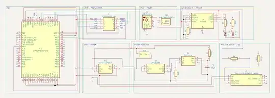
  • Electrical Schematic: Electrical Schematic

  • PCB test points I want to connect BT1 to: enter image description here

JRE
  • 71,321
  • 10
  • 107
  • 188
GildedWasp
  • 35
  • 4
  • 4
    I think there's too many unrelated questions. Schematic reviews are not very good questions in general, as they are very difficult to answer, how do you decide the best answer if all are correct but with different aspect of the circuit? But it has a lot of problems and for example reading the MCU documentation you would be able to answer all MCU related questions, and even fix problems you are not aware yet. – Justme Apr 13 '23 at 18:12
  • 1
    For the battery connection, make a 2-pin PCB footprint with pads and holes of suitable size for your battery wires, and link the battery schematic symbol to that footprint. – Peter Bennett Apr 13 '23 at 18:15
  • @Justme well if you look at my questions, I have quotes from the datasheet showing that I have "bothered" to read the datasheet and I am just not understanding it well. This question is pointed towards people with experience in ST's platform or can understand datasheet jargon. It's also important as someone new to the industry to know what is expected out of my drawings and circuits. There may be a million answers, but there are electrical standards for a reason. A schematic review is a good way for us newbies to be taught a little more depth into our trade by OG's. – GildedWasp Apr 13 '23 at 18:47
  • Sure, a schematic review may be good for you, but not for this site. This will likely be closed for "needs focus". – evildemonic Apr 13 '23 at 18:49
  • A new person getting feedback for their drawings is important. Any person trying to learn an ST MCU could come to this post see the answers and have an idea of how to use the same MCU I am. Another person seeing my drawings and you guys correcting me may also teach them to not do the same on their drawings. – GildedWasp Apr 13 '23 at 18:54
  • 1
    Have you searched for similar questions? For some reason, people seem to make the same mistakes despite datasheets, application notes and example schematics, so it is likely that many of your questions have been asked before, and have already been answered. – Justme Apr 13 '23 at 19:01
  • At that point to be a helpful community member you could just point someone in the direction of said post. You're making a comment based on something being likely and not actually the case. If you find one call me out otherwise your just starting drama. Reading the datasheet for these things would be faster than asking the question and going through the steps of proofing my questions for 30 minutes before I post. I understand you don't want lazy people, but I gave proof that I attempted to understand the circuit and all. – GildedWasp Apr 13 '23 at 19:08
  • Now you're downvoting me. I think I am going to stop using this site. How am I supposed to learn anything when you all act like this? – GildedWasp Apr 13 '23 at 19:20
  • 2
    You are right, reading the datasheet would be faster than asking questions. The web page for your STM32 contains a hardware getting started guide, and eval boards with that MCU provide example schematics. It's much faster for you to open and read those documents to fix errors, than having us do so and write how to fix them. It will also reduce the iterative cycle of updating the schematics and asking if it is now correct, and that invalidates many answers. Sorry but iterative schematic reviews are not just good fit for Q&A site, a more traditional forum would suite better. Didn't downvote. – Justme Apr 13 '23 at 19:23
  • 3
    Obvious things like decoupling capacitors (or lack of them) stand out. Lack of a plethora of test points with the ability to cut/wire things you get wrong first time is also a stand out. It's quite likely it won't work first time (unlike my designs because I've learnt the hard way and have a ton of experience) so, give yourself every chance of being able to fix it easily and develop extra IO on your MCU and add a plethora of test points you can probe and use for bodge wires linking cut tracks. – Andy aka Apr 13 '23 at 19:28
  • Where are your decoupling capacitors? – winny Apr 13 '23 at 19:48
  • Where should I have decoupling capacitors? – GildedWasp Apr 13 '23 at 19:50
  • 1
    @GildedWasp At the power entry for every IC. – evildemonic Apr 13 '23 at 21:16

1 Answers1

2

So, you need help with schematics.

Any one of those multiple separate questions you could and should be one specific question and you might receive a specific answer for that question. Now it's a big list of unrelated questions so any answer should address all of them, which is too much to ask.

However, to fix most problems related to MCU, please read the hardware getting started guide for your specific STM32 model, and maybe look at Nucleo board schematics how they have wired that specific MCU model.

Justme
  • 147,557
  • 4
  • 113
  • 291
  • As someone who is new to the site how would I know I can't ask multiple questions like that? If you can't answer all of it, then don't. I have never been on a forum before that cares so much about the format of how I ask my question. Just because you have 115k rep doesn't mean I do. I also think it's pretty messed up to pick me apart, because I don't know to ask a question to you or the sites standard. You're making all kinds of insinuations about someone you don't even know. You have no clue how much of that datasheet I've read and just not understood. – GildedWasp Apr 13 '23 at 19:36
  • 3
    @GildedWasp your first posted question was closed on needing to be more focussed with the closure comment clearly stating this: Update the question so it focuses on one problem only. This will help others answer the question. In addition this isn't a forum; it's a Q and A site that wants to showcase really good questions that meet the rules alongside really useful answers. You might be thinking this is a forum, but it isn't (not in my opinion anyway). – Andy aka Apr 13 '23 at 19:44
  • 2
    @GildedWasp Please calm down a bit. They are actually trying to help you. To get quality help, you need to understand how this site works. It is not a "forum". It is a question and answer site that maintains very high quality by being picky about what is allowed and what isn't. Nobody is "picking you apart" or being "messed up". The people writing to you are highly respected posters and genuinely trying to help you with their own free time. Please go over the Tour here if you need to: https://electronics.stackexchange.com/tour – evildemonic Apr 13 '23 at 21:13
  • I see the genuineness now, but don't act like he couldn't have approached it a bit differently instead of assuming I was lazy and didn't do a single bit of research. That was my only point and I have a right to feel some type of way about it. – GildedWasp Apr 13 '23 at 21:36