How to understand "ideal" things
The key to understanding ideal things is not in considering the ideal itself but rather the transition from the real to the desired "ideal". Thus, we will not only understand the ideal, but also know how to turn the real into an ideal. For example, if we want to understand why someone is rich, we have to start from when they were poor. In this way, we will understand the secret of getting rich and we will be able to get rich ourselves :-)
Understanding negative feedback amplifier
In this particular case, we need to look at what a real negative feedback amplifier does and then start making it "ideal". The best way to do it is through experiments - thought, simulation or real. They are all useful and necessary, but here it is most convenient to use the built-in CircuitLab simulator.
Circuit diagram
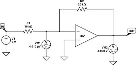
In order not to be distracted by details, let's examine the most basic negative feedback circuit - the op-amp follower. Its idea is extremely simple - to make the op-amp copy the input voltage, we connect its output opposite to the input source and apply the voltage difference to its input. In this way, we force it to set its output voltage equal to the input voltage.

simulate this circuit – Schematic created using CircuitLab
Note that both input and output voltage have the same positive polarity with respect to ground, but they are of opposite polarity as you move along the loop.
Operation
Let's explore the circuit operation with the help of CircuitLab starting with a "very real amplifier" (with very low gain) and gradually making it almost ideal (with extremely high gain). Here are some practical considerations about carrying out this simulation experiment:
1. It is convenient to indicate the voltages by voltmeters because that way we will immediately see the difference when changing the op-amp gain (another way is to hover the mouse over the labels IN and OUT but there is no way to do it with Vd).
2. As you can see in the schematic below, I have moved the voltmeters to the left. The reason for this is that the open op-amp properties window does not hide the voltmeters and you can observe how the voltages change as you set various op-amp gains (see the screenshots below).
3. Also, move the schematic to the left edge of the screen so that the properties window opens in its right part.

simulate this circuit
4. You can change the gain any way you want from 1 to millions. But in order to have some consistency, I recommend the following way that occurred to me today.
A_OL = 1. First set the smallest gain by writing "1" in the gain field and you will see that Vd = 500 mV (significant voltage error).

A_OL > 10. Then repeatedly press the "0" key (or hold the key) - the gain increases tenfold, and you can see how the op-amp input voltage Vd vigorously drops. To move in the opposite direction, press repeatedly (or hold) the backspace key. This way we mimic something like sliders in CircuitLab.
A_OL = 10e10. When you enter 10 zeros, the voltmeter shows zero.

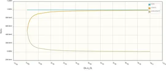
Varying A_OL. Now let's do it fully automatically with the help of the CircuitLab DC sweep simulation by varying op-amp open-loop gain OA.A_OL. To see the most interesting first part of the graphs, in the schematic above, I have set a sequence of gains (1,2,3...10,20,30...100); you can change it as you want. As you can see, the error op-amp input voltage rapidly decreases from 500 mV (gain of 1) to 10 mV (gain of 100).
Explanation
The simulator helped us to see the effect of the open-loop gain on the voltage error, but we need to explain what we saw; only then can we say that we have understood it.
Reversed amplifier. This experiment helped us to see something interesting in the op-amp behavior caused by the simple connection between its output and the inverting input - the op-amp itself changes (adjusts) its input voltage Vd to match its output voltage Vout, which in turn is set by the circuit input voltage Vin. It is as if the op-amp has been "reversed" - its output has become an input and the input has become an output... and it has become a kind of "attenuator" that reduces Vout to Vd A_OL times. Thus, the op-amp makes the difference between Vin and Vout negligible and Vout is almost equal to Vin.
Op-amp integrator. It is obvious that the op-amp that is forced by the negative feedback cannot act instantaneously when the curcuit input voltage Vin changes (see also a related answer of mine). Its "transition gain" A_tr = Vout/Vd is less than its open-loop gain A_OL and the op-amp needs some time to reach equilibrium when A_tr = A_OL. Only then Vout = Vin.
The three gains. So, my conclusion is that in total there are three gains: a temporary gain acting during the transition, an open-loop gain and a circuit gain of the op-amp follower. When the circuit input voltage Vin changes, in the first moment, the op-amp output voltage does not change. The transition gain is below 1 but it begins vigorously increasing and finally reaches the op-amp open-loop gain. Then the output voltage becomes (almost) equal to the input voltage.
"Op-amp follower man"
The best way to imagine what the op-amp is doing during the transition is to put ourselves in its place. That is why, I suggest you make, in the form of a fun game, a "follower man" in the likeness of the famous H&H "transistor man". But you will have to show a little more dexterity because CircuitLab is not suitable for such "frivolous" games:-)
Our "man-controlled follower" is extremely simple because, besides the man, it consists of only a variable source Vout and a sensitive voltmeter Vd acting as a null indicator; but as you will see from the experiment, it is almost perfect. Another interesting thing is that it was invented back in the 19th century when there were no op-amps (using a potentiometer for a voltage measurement).

simulate this circuit
As you can see, the two voltages are connected in series and in reverse in a loop so their difference is applied to the voltmeter. The only problem is that you will need to work with two voltage sources at the same time - once setting the input voltage via Vin and then gradually adjusting the output voltage Vout equal to Vin.


