1

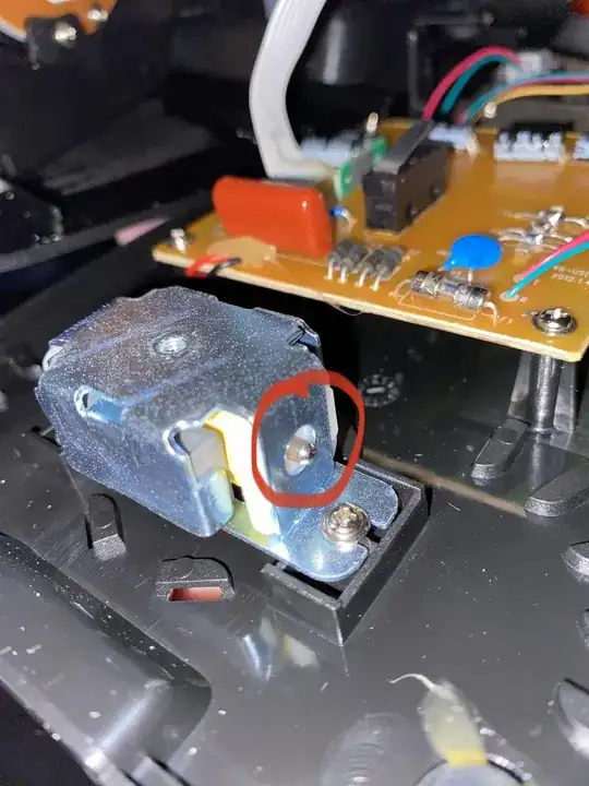
I’ve got a recently manufactured “retro” landline phone that I wanted to scavenge some parts from, made in 2012 I think. I’d like to be able to do something with the ringer, which appears a lot simpler and more low power than old rotary phone bell ringers. Anyone seen a motor/actuator like this? Trying to figure out what voltages I’m actually going to be working with. Wondering if I can power this with much smaller AC voltages than typical old phones.

The brass cup screws on over this little motor and you can see in the photos the driver rod which it has on both sides to actuate the bell—I assume it’s one rod/piston/driver… Any idea the part? I cannot find any part numbers on it…. The bell says “Hongfu Sound” which returns very little.

Image 1:
enter image description here

Image 2:

Edit:

Sorry not a retro phone at all, hence the quotations, it’s apparently still for sale below. That’s why I was super curious about the ringer motor because it seems like I could use this more easily with smaller power signals.
https://www.amazon.com/Wild-Wolf-Rotary-Landline-Telephone/dp/B07X5MSPX3/ref=mp_s_a_1_1?qid=1678582582&sr=8-1&srs=14625083011

Rp Wav
  • 11
  • 3

3 Answers3

1

This is a metal stick (clapper) from a bell.

The stick is ringing the bell and he can move because of this gray magnets on each side and a coil in the inside. The coil is wrapped around the metal stick.

The black and red cable are there for moving the stick against the bell. This is possible DC voltage what is used there. You apply a PWM signal with 50% on and 50% off timing to this red/black cable (black = GND, red is possibly 12V) and this will create the ringing sound.

So is possibly the technical solution of this phone.

You could use an other frequency and make the ringing a bit different if you want.

To drive this bell I would apply a voltage source to it and increase the voltage till the stick is moving out. The current can be high, maybe 1A.

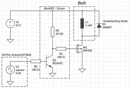
If you want to drive this bell, then add 12V to the red cable and a N-Channel Transistor (MOSFET) to the black cable. (Drain to the black cable, source to GND of the voltage supply and with the gate you can control the current flow)

Driver: enter image description here

R3 should be much bigger, between 10k Ohm and 100k Ohm would be okay.

MikroPower
  • 1,348
  • 2
  • 11
  • Those were my thoughts too, any idea what voltage/current would drive something like this? – Rp Wav Mar 12 '23 at 00:04
  • Hell yea that’s the answer I’m looking for and will try it. – Rp Wav Mar 12 '23 at 00:20
  • Any idea the nead for the massive film cap? Some kind of inductive kick? – Rp Wav Mar 12 '23 at 00:29
  • 1
    If the phone really is "retro" in operation it most likely relies on the simple 90V AC 20-24Hz voltage that the phone line sends for ringing the phone. The solenoid pin simple shakes with the AC signal and strikes the bell. The 4 diode rectifier may convert the AC signal for some other function or maybe for a different ringing tone. – Nedd Mar 12 '23 at 00:32
  • @Nedd - There is a little PCB in the Main-PCB with a microchip. This is from 2012, so the possibility that this is from the old time, is going to zero. Alone that they use there hot-glue is a sign that it is made in china and very young. – MikroPower Mar 12 '23 at 00:47
  • It’s a modern phone sold as retro which is which why I was wondering about the part. Yea, that 4 diode rectifier is something… wasn’t sure if it was still converting the 90VAC ringer voltage in 2012 or not. The ringer is small enough that I suspect not but not sure. – Rp Wav Mar 12 '23 at 00:48
  • @MikroPower I only noticed that little PCB in my photos. That is strange and will have to investigate. But yes, by “retro” I mean absolutely not and sold as such. – Rp Wav Mar 12 '23 at 00:50
  • Here is a link to a site with a simplified schematic for true "retro" phones. The capacitor may be used to block the 48 VDC of the POTS line and provide the 25 Hz ringer signal to the bell. http://users.utcluj.ro/~dtl/TF/Cursuri/LAB1_eng.pdf – PStechPaul Mar 12 '23 at 00:59
  • @MikroPower - Retro "in operation". – Nedd Mar 12 '23 at 01:01
  • Yea sorry guys I should have put 5 quotes over retro, this phone is modern [] which is which I was confused. [Edited by a moderator.] – Rp Wav Mar 12 '23 at 01:05
  • Another hint at the ringer is the bullet point in the Amazon description "Plugs into any standard phone socket for use - original style mechanical ringer ". As for the so called micro chip, that's a possibility but then it could also be a DTMF circuit using the dial buttons as input. There even seems to be a ceramic resonator mounted along side the piece too. – Nedd Mar 12 '23 at 01:56
0

It's a solenoid actuator.

...............

Davide Andrea
  • 21,104
  • 6
  • 34
  • 73
  • That’s an expensive lamb (part)! Are there versions that rotate back and forth with both sides exposed because that’s kind of how this looks—other side not pictured is the same—unless there’s two of these devices out of phase. – Rp Wav Mar 12 '23 at 00:40
  • 1
    "Are there versions that rotate back and forth". No. The plunger slides in and out of the channel. – Davide Andrea Mar 12 '23 at 02:21
  • Ok this is what I’m talking about though… the plunger goes back and forth https://imgur.com/a/KQ8B5VA This doesn’t look like any of the actuators you linked to above. – Rp Wav Mar 12 '23 at 02:43
  • 1
    Which is EXACTLY what I said! Which is EXACTLY how the solenoid actuators I linked above work! https://www.youtube.com/watch?v=xVk1CT3FWlo – Davide Andrea Mar 12 '23 at 15:09
  • 1
    Thanks for your kind help. – Rp Wav Mar 12 '23 at 17:34
  • 1
    Nothing says "thank you" more than an upvote and accepting an answer. https://stackoverflow.com/help/someone-answers – Davide Andrea Mar 12 '23 at 17:51
0

Without seeing more of the circuitry (bottom side of the board - ?) it's impossible to say for sure. Just guessing . . .

As above, the ringer is a simple solenoid. The armature oscillates back and forth with a high voltage AC sine wave. The phone company ring voltage is an AC sine wave sitting on a -48 V DC pedestal. C15 removes the DC component, so only the AC waveform reaches the ringer.

The four diodes for a bridge rectifier. They power the audio circuits, not the bell.

A POTS phone line is polarized, and old phones had no active electronics in them, so they worked no matter which way they were connected to the line. Modern phones have transistors, maybe opamps, etc, and these circuits most definitely are polarity-sensitive.

With a bridge between the lines and the electronics, the overall circuit is then polarity independent because the bridge steers the operating current whichever way is necessary for current to move through the circuits.

Here is a link to a typical electronic phone schematic from the 80's.

https://www.next.gr/uploads/135-10235.png

AnalogKid
  • 19,998
  • 1
  • 13
  • 32