-
1It's better to label the components with designators rather than values. However, are you familiar with star-delta transformations? – Neil_UK Mar 10 '23 at 12:19
-
See also: Analysing less trivial arrangements. – greybeard Mar 10 '23 at 12:22
-
I would make the 150-ohm resistance the extra element and apply the extra-element theorem or EET. It is fairly straightforward with impedance determination as a nulled response across a current source (the stimulus) is a short circuit. – Verbal Kint Mar 10 '23 at 13:10
-
Tuan - Hi, It is not allowed to deface a question, as a means of removing it (that is considered to be vandalism). Instead, if you have received a suitable answer, please see this article from the [help]. I have reversed that edit to the question. Thanks. – SamGibson Mar 10 '23 at 19:12
3 Answers
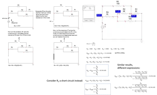
The fastest way for me is to apply the extra-element theorem or EET forged by Dr. Middlebrook years ago. This is a good example to exercise it and, as shown below, you obtain the answer in a well-ordered low-entropy form without writing a single line of algebra:
A resistance or an impedance is determined by applying a test generator \$I_T\$, the stimulus, across the connecting terminals of your input. You then determine the voltage response \$V_T\$ created by \$I_T\$. The ratio \$\frac{V_T}{I_T}\$ is the resistance or impedance you want.
You start by designating the element that causes troubles and impedes you from solving the circuit. Obviously, \$R_5\$ is the trouble-maker here and becomes the extra element. Then you decide if you remove it or replace it by a short circuit to determine the resistance in this intermediate step. I choose to remove it and solved the circuit by inspection. I could also have decided to short it instead and it is up to you to select the simplest circuit to inspect/solve (I added this solution in the drawing).
Once this is done, you proceed by determining the resistance \$R_d\$ "seen" from \$R_5\$'s terminals with a zeroed excitation (the 0-A source is removed). You then proceed by nulling the response \$V_T\$ and determine the resistance \$R_n\$ in this mode. It is easy because a nulled response across a current source is like replacing the source symbol by a short circuit. You finish the exercise by assembling the complete expression and, voilà, you have the total expression. A quick bias point in a SPICE template confirms this is the correct value.
The EET is part of the fast analytical circuits techniques or FACTs toolbox. Very often, the FACTs lead you straight to the answer without writing a line of algebra as in this example. Starting with the EET is a bit abrupt and I recommend you begin smoothly with my APEC 2016 seminar you can download from my page.
- 21,968
- 1
- 18
- 55
I would use Delta-Y transformations, but you may not have learned that. The first way you would probably learn to solve this would be Kirchhoff's laws.
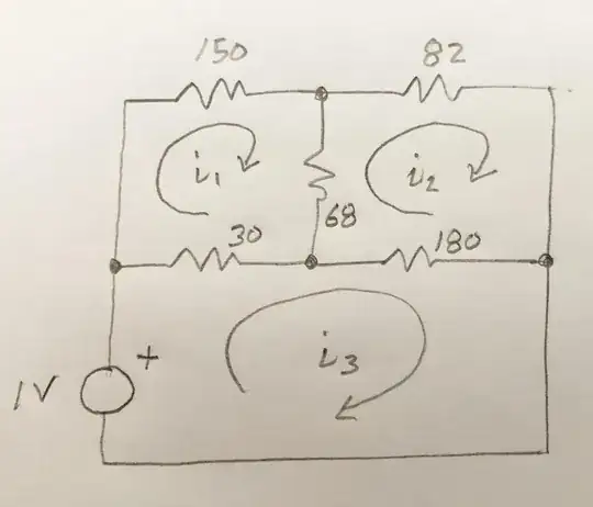
Redraw so the meshes are obvious. The equivalent resistance will be 1V/i3.
I get the same answer as Verbal Kint. Although I cheated and used an online calculator to solve the 3 equations with 3 unknowns.
- 15,935
- 1
- 20
- 47
-
It is not cheating, it's good engineering practice! : ) I assume the result is quite complicated and not really insightful in this way? – Verbal Kint Mar 10 '23 at 14:49
-
@VerbalKint Knowing the process is insightful; slogging through calculations is not so insightful – user253751 Mar 10 '23 at 16:19
-
@user253751, well, by insightful I meant the way the result is organized and if you can infer anything from it at first glance? Using FACTs and the EET lead to a compact result in which you see series-parallel terms that tell how elements combine together. – Verbal Kint Mar 10 '23 at 16:34
Apply Y-delta transformation to the Y network formed by the 150, 82, and 68 Ohm resistors. Afterwards, the circuit is just a trivial series/parallel resistor network.
- 18,288
- 34
- 56


