0

I have designed a PCB that utilizes a P-MOS as a high-side switch to control a 48 V battery using the following circuit. The P3 connector is connected to a momentary switch and a 5 V LED. The intended function is as follows: pressing the button (P3) should activate P-MOS, and the MCU command should keep it alive (keep enable). This design generally works correctly, but there is one issue:

When I connect a battery to the circuit (live insert), I can see a blink on the output LED (voltage on +48VDC_Init) for a short time (less than 100 ms). It seems that upon battery connection there is a short time voltage on the output side and then it goes off. I wonder if anyone has any recommendations to solve this issue.

Thanks
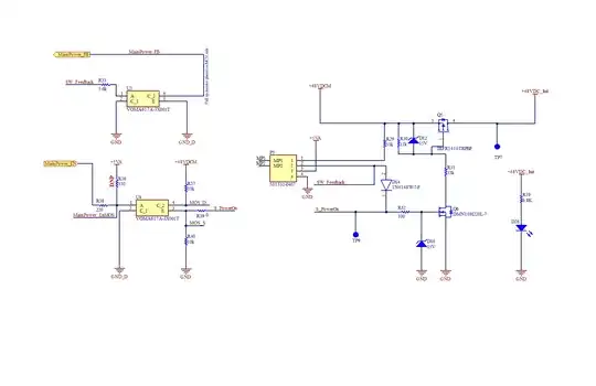
enter image description here

winny
  • 14,707
  • 6
  • 46
  • 66
Hamed
  • 1
  • 2

1 Answers1

3

You need a gate-source resistor on Q6 to keep it off. 100 kΩ is probably enough.

winny
  • 14,707
  • 6
  • 46
  • 66
John D
  • 23,824
  • 1
  • 41
  • 61
  • R30 is installed from gate to source. Maybe the drain-gate capacitance of Q6 is causing it to turn on. There should also be a capacitor from +48DC_link to GND to avoid high dV/dt surge when hot-connecting. And also from 48VDCM to GND. Or, maybe a capacitor across R30? – PStechPaul Mar 07 '23 at 22:38
  • 1
    @PStechPaul I was thinking of a gate-source resistor for Q6, not Q5. There's nothing but the leakage current/capacitance of D16 to keep the NMOS off, so I'm thinking that the gate-drain capacitance of Q6 is pulling the gate of Q6 up enough to blip Q5 on. – John D Mar 07 '23 at 22:46
  • Yeah, I didn't read your answer carefully enough. That may be the problem. And perhaps a capacitor there as well. Switching speed is not an issue, and current will be low enough to survive a slow transition through a linear region. However Q5 may carry high current, where fast switching is important. – PStechPaul Mar 07 '23 at 23:06
  • @PStechPaul Actually, I have a 10k gate-source resistor on Q6(before R32 (TP9)). But, It happened. So, adding a capacitor to +48DC_link to GND can be helpful? – Hamed Mar 08 '23 at 05:56
  • @JohnD Actually, I have a 10k gate-source resistor on Q6(before R32 (TP9)). But, It happened. So, adding a capacitor to +48DC_link to GND can be helpful? – Hamed Mar 08 '23 at 05:56
  • 3
    @Hamed If your circuit is different from the one you presented, i.e. you have a gate-source resistor not shown on your schematic, you should edit your schematic to reflect your actual circuit. It's difficult to answer a question if we have to work with a schematic that's different from what you have implemented. – John D Mar 08 '23 at 05:57
  • There should be capacitors on both input and output. But I don;t know what value to recommend. Probably around 470 nF. Hot connecting with 48V might be tricky. – PStechPaul Mar 08 '23 at 06:06
  • @JohnD Yes, you are right. I've updated the schematic. I enable the MOSFET using an optocoupler and also get feedback using another optocoupler. – Hamed Mar 08 '23 at 07:00