I am learning about voltage divider circuits and how they work. Here's an image as example:

After the voltage from Vin goes through two resistors, after the second resistor, does it have to end up at ground (aka the 0 V point)?
I am learning about voltage divider circuits and how they work. Here's an image as example:
After the voltage from Vin goes through two resistors, after the second resistor, does it have to end up at ground (aka the 0 V point)?
No, it does not have to end up at 0V.
It can end up being connected to any voltage required to perform the operation you need, such as dividing +/- 5V input range to a single-ended ADC with 0 to 5V range.
Voltage does not go in or through. Voltage is applied across an element or collection of elements. Current travels through elements.
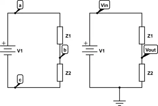
The diagram below shows two circuits: One without a ground symbol, and another with a ground symbol.
The voltages \$V_{in}\$ and \$V_{out}\$ are assumed to be with reference to ground. On the left, The voltage \$Vac\$ uses double-subscript notation to specify the nodes that the voltage is measured between. Comparing the two diagrams \$Vin = Vab\$ and \$Vout = Vac\$
\$V_{in}\$ and \$V_{out}\$ use single subscript notation to indicate that the voltage is referred to ground.
Ground should be considered a reference for measurement and/or a connection to local earth. It really has no effect on circuit analysis except to establish a 0 volt reference.
If there are several ground symbols on a diagram, they serve to show that the points are electrically connected together and to be considered 0 volts.
simulate this circuit – Schematic created using CircuitLab
No, Ground basically considered as reference voltage, from which we can say that, the range of Vout will be in between 0 to Vin. If we connect voltage (Vo) in place of ground, the range of Vout will change from Vo to Vin (w.r.t ground). Just like a Potentiometer.