1

I have added a simple power source for my LTV-3120 IC that I want to use to drive a MOSFET.

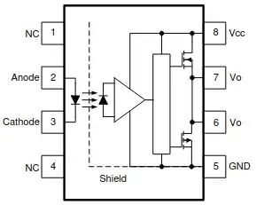
LTV-3120: enter image description here

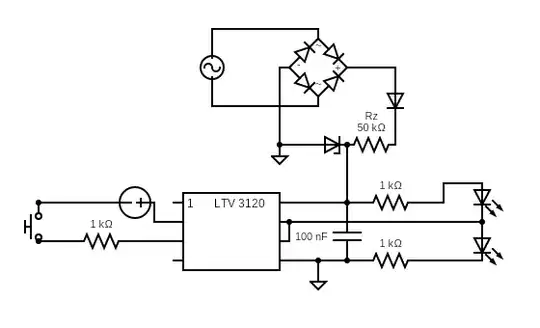
The "power source" is a 220 VAC rectifier with a 20 V Zener diode and 50 kΩ Rz.

enter image description here

With this, I can measure ~20 V on the Zener diode, but it seems like the LTV-3120 is not reacting when this is used as a power source. One LED is on, but when I press the button the second one never lights up and the first one shuts down, so it's basically not working the same way as when I had too little voltage on the IC. When I try the LTV-3120 with 2x 9 V in series it works as expected.

I have tried 100 kΩ, 50 kΩ, and 33 kΩ for Rz by putting a 100 kΩ resistor in parallel, but no effect.

What is my mistake?

The scheme above is for testing purposes, uses LEDs and button. In reality: this IC driver will drive this MOSFET on the low side (I think).

Q1: How can I improve the current schema, and which values to choose for the capacitor and resistor in order to accommodate this test schema and also MOSFET?

Q2: If I would use a battery to power the LTV-3120, do I connect its ground to the source of the MOSFET?
Null
  • 7,603
  • 17
  • 36
  • 48
greengold
  • 175
  • 7
  • 1
    Your circuit has pulsed DC across the tiny capacitor. That aside, your schematic requires everyone to look up the pin-out of the LTV-3120. Please redraw the schematic to show the internals of the LTV-3120. Please don't just paste the LTV-3120 datasheet diagram underneath the schematic, that requires readers to piece it all together. Thanks. – TonyM Feb 19 '23 at 16:38

2 Answers2

2

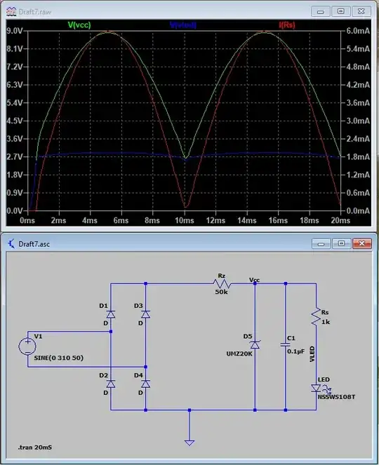
The supply across Rz and with such a low capacitor for 100 Hz, cannot supply more current than 6 mA peak. A LED connected to 20 V with a resistor of 1 kΩ, will demand more than 15 mA.

So Vcc voltage peak will be about 9 V with the values in your circuit, and minimum recommended for this driver is 15 V. That could explain the weird operation.

Check again if Vcc is 20 V with the LED´s connected, in case is lower, increment 1 kΩ resistor to reduce current and also C1 to filter low frequency. See simulation of one LED directly to the supply.

enter image description here

EDIT: The driver datasheet states Icc= 3.5 mA max, but you have to add the current for switching the gate. The driver can output 2.5 A peak, the average current will depend of switching frecuency and Cgate, better to test with external supply. The supply for the driver GND must be connected to same power bridge for the MOSFET. The Zener diode can handle a limited power, that will be the restriction to reduce the resistor Rz. (for example 0.5 W / 20 V, will support max 25 mA; Rz = (310 -20 V) / 25 mA = 7.6 kΩ). This configuration will cause high permanent heat losses (about 5 W).

Other possibilities more efficient are: transformer from the grid, rectifier and filter; also AC-DC switching adapter isolated (may be cheap wall adapter). Of course connect GND to source.

enter image description here

winny
  • 14,707
  • 6
  • 46
  • 66
Bravale
  • 1,557
  • 5
  • 8
-1

The upper LED can not be turned on because it is connected across the upper switch. It will be shorted by the switch between pin 7 and 8.

The lower LED will turn on when the button is pushed and the switch between 7 and 8 is activated.

But if the supply is strong enough both LEDs will be turned on all the time because they are connected to the supply in series through 2 kΩ resistors.

ocrdu
  • 9,195
  • 22
  • 32
  • 42
  • You've read the circuit wrong. The LTV-3120 has a push-pull output driver: one output FET is always on, the other FET always off. So when the upper FET's on, just the lower LED is lit. And when the lower FET's on, just the upper LED is lit. Downvoting, I'm afraid. – TonyM Feb 21 '23 at 19:35
  • But both will be on all the time because both are connected across the supply. Don't you agree? – Abrahamt Feb 21 '23 at 20:10