7

I am designing a circuit which will control many electromagnets. Shift registers will be used (74HC595) to control MOSFET gates directly, with proper gate resistors (the MOSFETs will be switched at most at 200 Hz, so switching time is not really a concern).

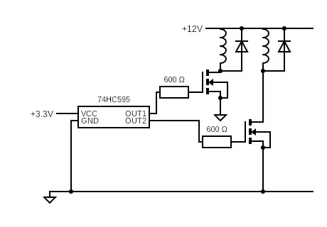
Here is a reduced version of the circuit (in reality, there will be more magnets, MOSFETs, diodes, and shift registers):

circuit

Each electromagnet passes 2 amps when saturated. So far, I've selected the following parts:

  • MOSFETs: PMV20EN, logic level MOSFET (Vgsth=1.5V), Vds=30V, Id=7.6A.
  • Flyback diodes: 1N5404 (400V 3A)

The 74HC595 can output a maximum of 70 mA, and the 600 ohms resistor limits the current to 5 mA per output. This should still give a switching time of a few microseconds, which is perfectly fine.

Am I missing something, or should this be fine?
Bradlin
  • 75
  • 3
  • 4
    Welcome! Seems reasonable. 3 A continuous rating on the diode but you're after peak current here. I would look for at least 100 % margin on peak current rating (4 A) versus your 2 A coil. Do you have decoupling capacitors on your 74HC595? – winny Feb 16 '23 at 14:25
  • 1
    @winny I will go for 4A diodes then. I hadn't thought about decoupling capacitors, I will also add them, thanks! – Bradlin Feb 16 '23 at 14:32
  • Looks fine to me. I didn't know there were MOSFETs that can pass 2 amps with 3.3V gate voltage :) – user253751 Feb 16 '23 at 14:50
  • Solenoid limiting resistance is what value? How low might it be and how high? – Andy aka Feb 16 '23 at 15:53
  • 2
    Be aware that Vth of 1.5 V doesn't necessarily mean the transistor will be usable as a switch at 3.3 V. This one will, but you have to scroll down to figure 8 to see that. – Hearth Feb 16 '23 at 16:25
  • 1
    @winny The 1N5404 is rated for 30 A peak repetitive surge current; I think there's little risk here. Though surge ratings can differ a bit between manufacturers. – Hearth Feb 16 '23 at 16:29
  • 1
    @Hearth Perfect. My point towards OP is that continuous current rating is not an ideal metric for choosing a diode for this application. – winny Feb 16 '23 at 16:33
  • @Andyaka the solenoids are given for 2A max current at 12V, and that's what I'm getting in my tests (between 1.8A and 2.2A), so that's a 6 ohms resistance. – Bradlin Feb 16 '23 at 16:39
  • FYI, since the diodes aren't carrying continuously, the peak rating is fine. A 1N4004 is rated 30A peak, plenty of headroom. Or say, US1G, or zillions of others. – Tim Williams Feb 16 '23 at 19:57

1 Answers1

7

A few notes:

  • 600 Ω is a very large gate resistor, but since you're switching at low frequencies that should be okay. I would be more likely to use a gate resistor in the range of 5~50 Ω, personally.
  • As winny points out in the comments, continuous rating isn't what you need for the diodes here, it's surge rating. They will experience a current surge starting from 2 A and approximately linearly falling to zero every time you turn off the switch. The rate of that decay depends on the forward voltage of the diode and the inductance and resistance of the coil. You should get diodes with a repetitive surge current rating greater than 2 A, preferably at least 3 or 4 A; the 1N5404 has a repetitive surge rating, according to this datasheet of 30 A, so you're fine there. Bigger than you need, but there's no harm in it.
  • The MOSFETs are suitable, but note that Vth alone is not the parameter to use to determine if they'll work with 3.3 V drive. To fully turn on a MOSFET, the gate-source voltage needs to be a few volts higher than Vth--Vth is not the voltage at which the FET is on, it's the voltage at which the FET stops being off. There's a few volts of linear operation (to be avoided in switching FETs!) between there and fully on. For this device, you have to go to page 7 of the datasheet and check figure 8 to see that the on resistance is still pretty low at 3 V on the gate and 2 A through the drain.
  • You may want to add pull-down resistors to the gates of your FETs, to ensure they stay off if the 74hc595 loses power. I'm not sure what 74hc outputs do when Vcc is lost, but they might go high-impedance, and floating FET gates are just asking for trouble.
Hearth
  • 32,466
  • 3
  • 55
  • 133
  • large gate resistor it's a non-oversized transistor with a surprisingly small gate charge, too. – greybeard Feb 16 '23 at 17:25
  • There should also be a bypass capacitor between GND and +12V (around 1000uF, >= 16V would be fine), near the MOSFETs and diodes (diode associates with the switch, not the load). Probably with the 600R gate resistors, it's slow enough that "near" can be 10s of cm. – Tim Williams Feb 16 '23 at 19:58
  • Also (as always) an appropriate power supply bypass capacitor on the 3.3V supply of the 74HC595. About 100nF should be fine. – PStechPaul Feb 16 '23 at 20:51