3

Assume I have 2 flipflops FF1 and FF2 which are driven using multiple clocks. What might be the possible violations that we would come across? I was asked this in an interview for which I answered telling the difference in skew or the clocks would cause timing violations and metastability and further explained how to solve setup/holdtime violations . But in the end interviewer said these issues come into picture only when we use a single clock with skew/delay between the clock inputs of the 2 flipflops. So I was wondering if anyone can tell me what happens when I use multiple clocks

schematic

simulate this circuit – Schematic created using CircuitLab

Rancho
  • 141
  • 5
  • Wow I dint know about the schematic editor! Interesting! – Rancho Apr 12 '13 at 08:51
  • 1
    If the clocks are significantly different a kind of aliasing can occur - this applies when clk 2 is lower than clk1 – Andy aka Apr 12 '13 at 10:03
  • 1
    Did the interviewer draw them as edge or level triggered FF's? He was trying to get you to discuss how multiphase clock schemes reduce/eliminate the skew problem and enable a more robust solution vs. a single phase edge triggered scheme. – placeholder Apr 12 '13 at 10:29
  • No this was a telephonic interview and his FFs were edge triggered. Do you know of any link which describes multiple clock usage and it's problems or advantages? – Rancho Apr 12 '13 at 10:36
  • @Rancho CLK1 will be clocking data through the logic at a decent fast pace and if CLK2 is going slower than CLK1 it may "miss" vital changes in the output of the logic - almost like you are sampling a signal too slowly - you can get aliasing effects that make a mess of things. Look up aliasing – Andy aka Apr 12 '13 at 10:41
  • Doesn't that imply metastability? The output would be an unpredicted value since the data from FF1 might not be captured at FF2 and might have a wrong value? Ok I will dig into aliasing – Rancho Apr 12 '13 at 11:00

2 Answers2

3

The interviewer was simply mistaken. You always have to think about setup/hold time violations and the resulting possibility of metastability when considering signals passing from one clock "domain" to another, regardless of whether the clocks are "nearly synchronous" or completely asynchronous.

For signals that make transitions at a rate significantly slower than either clock, you can usually use double-FF synchronizers. In other cases, you'll need to use true asynchronous FIFOs, possibly with some sort of flow control or handshake mechanism.

Dave Tweed
  • 172,781
  • 17
  • 234
  • 402
  • One may in some sense have to "think" about them, but there are many real-world situations in which the nature of at least one clock's source will guarantee that the two inputs will never be clocked anywhere near each other, so the "thinking" may not have to extend to anything beyond "These inputs are always going to switch at least 10us apart; the s/h times on the second latch are 2ns and 5ns. Since 10us is greater than 5ns, there's no problem". – supercat Apr 12 '13 at 15:38
  • @supercat: If you can say that, then you are dealing with clocks that are in the same domain, and my comments don't apply. – Dave Tweed Apr 12 '13 at 15:41
  • Perhaps I don't understand exactly what is meant by "domain"? Suppose two independent clocks at 3.00MHz and 3.14159Mhz pass into T latches whose inputs are double-synchronized with "enable" signals, and the device which controls the enable signals will disable one latch for at least 1us before enabling the other. If the outputs of those T latches were used as clocks, would they be considered to be in the same domain or different domains? – supercat Apr 12 '13 at 16:00
  • @supercat: OK, with intermittent clocks, you're not talking about synchronous design techniques at all, and you have to apply full asynchronous design rules. Obviously, in this particular situation, you can come up with some ground rules that avoid metastability, but you at least had to "think about" it in order to get there. – Dave Tweed Apr 12 '13 at 17:00
  • By different CLK domains he just meant clocks which are independent. We are used to seeing the same clk being fed to all FFs(synchronus designs) in our courses . So from what I have learnt, I could think of only meta stability and timing violations. By multiple domains, I doubt if he meant the clocks were just a bit apart. I assume something like 2&4MHz or 5&10MHz(Maynot be real world examples). I din't question back much since I dint want to show I knew nothing about multiple clocks. So I just answered what I knew! Thanks for the answers. I will; do more research on this. – Rancho Apr 12 '13 at 17:21
  • @Rancho: It's curious that an interviewer would suggest that metastability is only a problem when there's a single clock source; if one clock is so much faster than the other that the high and low times of the slow clock are both at least two periods of the fast one, one can avoid metastability pretty easily by synchronizing the slow clock with the fast one. Things are much harder if one neither clock is known to be much slower than the other. – supercat Apr 12 '13 at 17:51
  • @DaveTweed: How difficult is it to combine synchronous and asynchronous logic in a design? I've noticed a lot of ARM-based controllers either really minimize the amount of async logic, or add annoying synchronization logic between it and anything to do with the core; from a practical perspective, it may be easier in software to deal with the fact that setting a "wake-up" alarm on a 32,768Hz async counter at the moment it increments could generate a false event, than have to wait two 30us after requesting an alarm before it can be changed. If software disables the interrupt before... – supercat Apr 12 '13 at 18:45
  • ...writing the alarm time, clears the interrupt flag, and then checks that the clock hasn't advanced before it enables the interrupt flag (if it has, repeat the whole procedure), it would be possible that the interrupt flag would go metastable, but software would never enable it in any situation where it might be metastable. Would the design tools balk at any attempt to create such a design (since the tools would see that the latch could go metastable, but wouldn't know that software would anticipate such condition and ensure it didn't actually cause a problem)? – supercat Apr 12 '13 at 18:48
  • @supercat: In what way is synchronization logic more "annoying" than implementing the elaborate software protocol you have outlined? In general, design tools will do what you tell them; at most, you'll get warnings about possible setup/hold time violations. In addition, most tools have ways to suppress those warnings on specific paths for which you have made other arrangements. – Dave Tweed Apr 12 '13 at 20:59
  • @DaveTweed: Any time one is setting an alarm for what should be a future time, it's a good idea to check--after setting the alarm--to ensure that it still is a future time. If the only synchronization-related latch is a "match" flag which shares a clock with the counter and grabs an asynchronously-generated comparison result, then if the counter hasn't moved while the alarm was being set, one will know that it's set properly. If the programmed alarm value matches the count value, the wakeup will occur on the next count cycle. If the alarm register is double-synchronized... – supercat Apr 12 '13 at 21:15
  • ...the earliest alarm one can set will be two 32Khz cycles in the future. Worse, on a number of processors with such wakeup features, if one sets an alarm for some distant future time, goes to bed, and gets almost immediately awoken by some external stimulus, one won't be able to begin setting the alarm for a closer time until the earlier request has fully propagated through the synchronizer. It thus becomes necessary to handle wake-up events which are supposed to occur within the next four clocks differently from those for more distant times. – supercat Apr 12 '13 at 21:20
  • @DaveTweed: One thing many hardware people don't recognize is that it's often not really any harder in software to do something and retry it if it failed, than to wait until something can be done and do it; if the operation takes e.g. 50 cycles and would almost always succeed on the second attempt if not the first, spending up to 100 cycles is a lot better than spending up to 2,000-3,000. – supercat Apr 12 '13 at 21:27
  • @supercat: I agree, it sounds like the hardware designers did not adequately consider system-level issues in that case. There's really no need to double-synchronize the alarm register, when all you really care about is the output of the alarm comparator. A different hardware implementation would be much more software-friendly. – Dave Tweed Apr 12 '13 at 21:50
  • @DaveTweed: I don't know why there are so many different programmer-hostile "real-time clock with alarm" designs out there. It would seem like it should be simple to design a 47-bit counter with a 32-bit comparator that could allow an alarm to be set for any future half-cycle of the 32KHz clock and take immediate effect; code which wants to set an alarm or read the full 48-bit value would have to do a try/test/retry, but such logic would be a good idea in robust systems even without metastability issues. Incidentally, one processor's RTC has a curious feature: ... – supercat Apr 12 '13 at 22:10
  • ...a register which can instruct the alarm comparator to ignore the bottom 0-7 bits of the counter. Supposedly this will reduce power consumption, but I'm not sure why it should; if each bit of the counter starting with the MSB generates a "match = (upper_bits_match & Cnt0 & Comp0) or (upper_bits_match & !Cnt0 & !Comp0)", the bottom bits of the counter wouldn't cause any transistors in the comparator to switch until the upper bits matched, so dynamic current draw should be basically zero. One might not want to require the compare to ripple through all 32 bits, but... – supercat Apr 12 '13 at 22:13
  • ...generating a "match" signal for the top 24 bits and then feeding that into a chain for the bottom 8 should still work to minimize dynamic current consumption. – supercat Apr 12 '13 at 22:17
1

The question is confusingly asked, which might have been the whole point of it, as it mixes up some concepts from different aspects of what is know as "open loop synchronous timing". He might have been looking for you to clarify a few key concepts. Open loop in this context means that the delays/phase is uncontrolled. Here is a brief overview to point into the direction at great simplification.

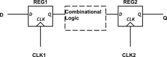
1) Global clock, edge triggered. What most people think of wrt to synchronous logic. The most popular for low end logic design because the edge triggered FF gives a simple model of sequential design, secondly, edged triggered FF are common deriving from TTL,CMOS and into the standard cell libraries that replaced them and thirdly most logic design courses only cover edge triggered designs. - the draw back is that there are two constraints: The maximum delay of the logic must be less than a limit for the circuit to operate with a given cycle time. The minimum delay must be greater than a limit related to the clock skew for the circuit to operate at any clock frequency.

The minimum delay on the logic:

\$ t_{d,logic} \ge t_{skew}+t_{hold}-t_{prop,c->Q} \$

The minimum cycle constraint is:

\$ t_{cy} \ge t_{d,logic} +t_{skew}+t_{setup}+t_{prop,c->Q} \$

2) level sensitive, dual phase clocking. Is perhaps the highest volume design regime. because this is what is used in uprocessors and more complex devices. Of course there are many variants on this, here we just look at the non-over-lapped clock version. The logic is divided by the master and slave FF's and the minimum cycle time is limited only by the prop time of each logic block and the clock-> Q of the FF's. Clock slew (with in limits) does not figure into these designs and as a result they are more robust, faster and smaller. It's not clear to me why this isn't taught as often.

\$ t_{cy} \ge t_{d,logic1} +t_{d,logic1}+2t_{prop,c->Q} \$

This second case when there is no OL clocks, and there is no second logic block reverts to the first case.

3)Pipeline timing: which we'll not discuss here.

placeholder
  • 30,170
  • 10
  • 63
  • 110