I would like to better understand how noise is radiated.
Suppose the circuit under study is a circuit with a DC/DC converter (source of noise) and an analog circuit (receiver) which is very sensible to noise as it has a large bandwidth (~100 MHz) and so can receive high frequencies.
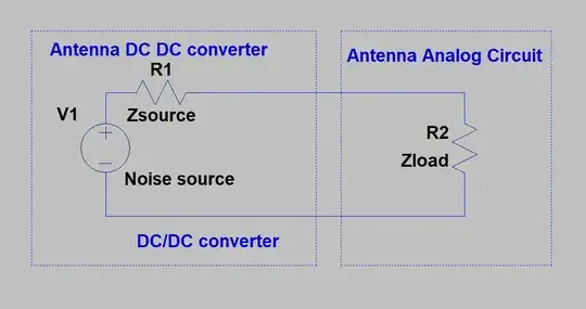
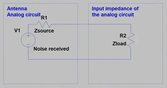
The DC/DC converter works as an antenna which send a signal (noise) to the antenna of the analog circuit. Depending on the impedance of the antenna the noise is more or less coupled. Then it also depends on the input impedance of the analog circuit. I imagine something like this :
and then :
What I do not know is the impedance of the antenna formed by a trace or whatever is the source or the "load". So it is complicated to say if the noise will be well-coupled.
My theory may wrong. Could someone apply some math to it using the above example? Then it will possible to say something about the noise coupling between traces.
-------------------------------EDIT-------------------------------------
I will try to more precise my problem and answer to the questions coming from the comments.
Firstly, what I would like to know is a better understanding of how noise is radiated between differents part of a circuit. If you have any documentation or keyword, I will appreciate it.
For the DC/DC converter working as an antenna : There are in a DC/DC converter some loops with high di/dt, so I was thinking that it would be possible that the loops could work as an antenna. It seems also possible that pcb traces, even if there are grouded, can work as antenna.
For the frequencies : I do not mention frequencies and patterns as I prefer that the question remain general. But for pratical purpose, a part from really bad layout, I do not think that it is possible to radiate/pick up noise inferior to MHz ?
I also precise that filter are difficult to set as the bandwidth of the analog circuit is around 100 MHz. I can put a filter with a crossover frequency at 100 MHz with a sharp roll off. There is still a bandwidth where noise can be radiated (~ 1MHz to 100 MHz) to the analog circuit
To more clarify the question, I was thinking that it was possible to see how the noise is coupled by knowing the impedance of the "load", let's say 100 kOhm or 1MOhm, and the impedance of the "source" of the receiving antenna. And adding the gain between the two antennas ? Finally figure out under what circumstance in term of pcb traces it is possible to achieve a good coupling.

