1

How would you create a rotating magnetic field using 4 big electromagnets located equal distance around the DUT. The magnets are configured in pairs of two (magnets opposite each other), controlled by bipolar PSUs (2) in Constant current mode (the value which is changing).

enter image description here

Excuse the horrific picture but it should help visualize the problem. My question is what mathematical formulas would i need to create a rotating magnetic field using these, or what documents could i read to help get me there?

This will be software defined so formulas/mathematical solution is needed.

Any clarification, ask, and i will edit the question with it.

super7800
  • 31
  • 4
  • 5
    Configure your PSUs to produce sine outputs at the same frequency, but 90 degrees out of phase. – brhans Jan 19 '23 at 18:56
  • 6
    You're pretty much describing a stepper motor, with microstepping – Tom Carpenter Jan 19 '23 at 18:56
  • 5
    so just set one to sin and the other to cos? – super7800 Jan 19 '23 at 19:14
  • 3
    Instead of “psu” the conventional terminology would be “h bridge” or “motor driver” - essentially you’re building a two phase motor (like a stepper mentioned above). – Bryan Jan 19 '23 at 19:18
  • @super7800 you want to give that as an answer? You seem to have got there. – Neil_UK Jan 19 '23 at 19:29
  • so to get one complete field rotation, i would start at 0, bring sin cos to max, then to min, then to zero again? (One complete waveform)? this is probably a simple question but i just cant seem to wrap my head around it. The DUT is a sensor not a motor. – super7800 Jan 19 '23 at 20:24
  • yes, "horrific picture". The basic form with sin/cos current drive to opposing coils does produce a rotating field. A magnet in the middle should rotate with the field, but not likely with a constant torque. Pole face shape, placing affects this. Note that sin & cos never are zero at the same point in time, so there's an anomaly at start-up and shut-down. – glen_geek Jan 19 '23 at 20:29
  • You could just pull the stator from a PMSM. All the techniques for a rotating field would be readily available (space vector modulation). – John Birckhead Jan 19 '23 at 20:32
  • 1
    @super7800 you would need an 'initialisation' phase, where you go from 'off' to a specific start angle. If the start angle is 0, then cos(0)=1, and sin(0)=0, but you could start with any angle, and use the appropriate values of sine and cos. Increment the angle through 360 degrees to get one full rotation of the field. – Neil_UK Jan 19 '23 at 21:23

1 Answers1

0

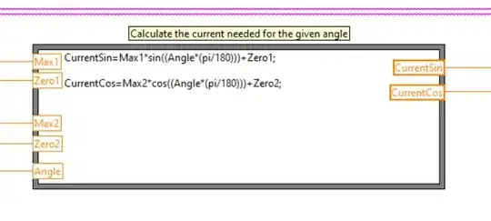
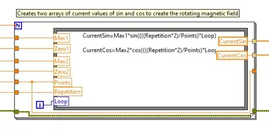
thanks to all. yeah, like always I was overthinking it. Here's how I ended up doing it (in LabVIEW). max and zero refer to the current required for that set of magnets at maximum field and at zero field. One accepts 0-360 angle values, the other creates a full array all at once from the required "measurement points" and "rotations". Hope this helps someone!

super7800
  • 31
  • 4