1

Apologies for the not so clear title, but I don't know if there is a common phrase that describes the point of concern.

I am taking an online course about input filter design interfacing the grid and a rectifier. the LC filter as is would not suffice because it has a "resonance" frequency at which the impedance is infinite. this point will ruin the entire system performance of the power electronics rectifier and the regulated voltage at the load.

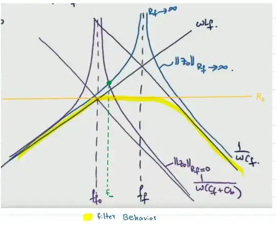
In damping the LC filter, we opted for a series RC in parallel with the LC filter as seen in the figure. Which brings us to my problem, the instructor mentioned that there exist a frequency f_m at which the impedance remains constant, no matter what the value of the added R_f. As you can see in the Bode plot, R_f=0 and R_f=infinity are plotted and there is a point that appears in both cases which is marked at frequency f_m. The instructor quickly mentions that this point will be there no matter what the value of R_f is. enter image description here
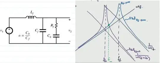
I tried to draw the bode plot by inspection for different R_f values enter image description here
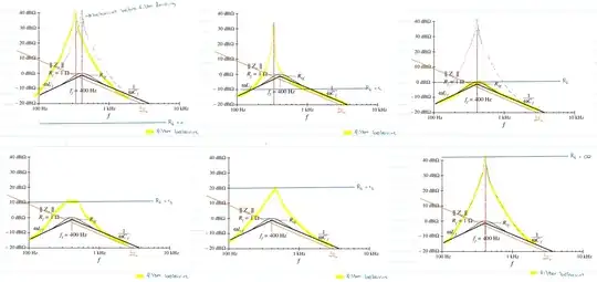
but It appears to me that there is no such frequency f_m which is unaffected by R_f

enter image description here

-----------------Edit----------------

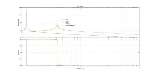
I plotted the transfer function in matlab, and there is indeed a point(f_m) where changing R_f doesn't influence the impedance. enter image description here
winny
  • 14,707
  • 6
  • 46
  • 66
amidher
  • 115
  • 8
  • 2
    I believe this is the point I show p121 of my APEC 2017 seminar on EMI filters. Considering the schematic you provided, this is material coming from CoPEC? – Verbal Kint Jan 17 '23 at 06:36
  • @VerbalKint thank you for referring to your seminar, very informative. The course I am currently taking is by Dr.Dragan Maksimović from university of Boulder. The schematic from his book "Fundamentals of Power Electronics" – amidher Jan 17 '23 at 07:21
  • The determination of the point that is insensitive to $Q$ is quite complicated but it is necessary to find the optimal couple of damping $RC$ values. It is important to include all the parasitics, especially ohmic losses such as $r_L$ and $r_C$ as they play a role in damping - read power dissipation - and lower the $Q$ in the end. – Verbal Kint Jan 17 '23 at 07:25
  • this point will ruin the entire system performance of the power electronics rectifier and the regulated voltage at the load <-- why? I don't see how it would providing you avoid that resonant point. – Andy aka Jan 17 '23 at 09:33
  • @Andyaka the seminar VerbalKint provided covers that in good details, we can represent the systems transfer function using the Extra Element theorem (the filter is the extra element), from there we can see how the the filter impacts the transfer function. you will notice that the system is disturbed with huge phase delay. Refer to the slides from VerbalKint 90 onward – amidher Jan 17 '23 at 10:11
  • Just a note in passing: alternatively, the virtual damping method is a tried and tested one that's likely to give much better results, at the cost of some complexity. – a concerned citizen Jan 17 '23 at 11:46
  • @aconcernedcitizen do you have any references in mind to read more about the virtual damping method? – amidher Jan 19 '23 at 05:56
  • 1
    @amidher This is a quick answer I gave a while ago. In addition you could search for "active LC damping" (or LCL), there should be some papers/dissertations/theses/etc laying around. – a concerned citizen Jan 20 '23 at 07:11

0 Answers0