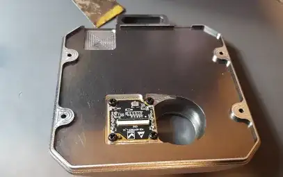
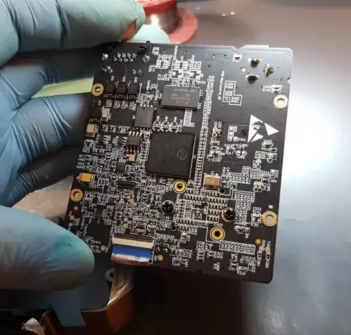
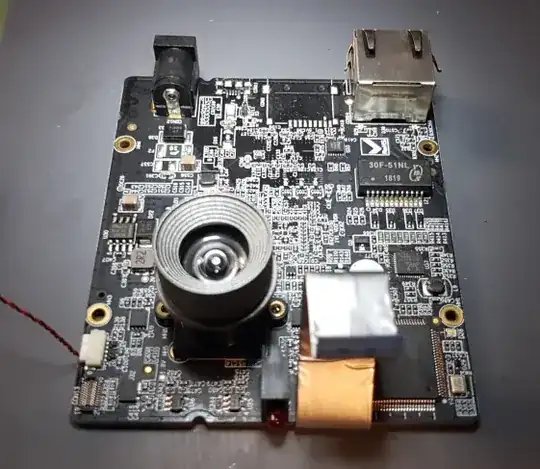
Having this Qunali IR cam which has a USB connector left out at the assembly and comms only via LAN. Probed Data lines, and I got 0.9V fluctuated readings. It seems to send something out there.
So was wondering if anyone could lead me to what values standard MicroUSB break-out lines would have.
- U26 Seem to have tree pins with middle to ground. Maybe a two-way diode?
- R4 is a pull-down resistor to the ground - Maybe 15k, looking at these guidelines? https://beyondlogic.org/usbnutshell/usb2.shtml
- R1 cannot trace where it goes, but it doesn't look like a pull-up to 5V
- D16, is that a Zener diode sign? Maybe 5V or a reverse polarity diode, as it is between the Fuse and ground.
I've populated F1 and L1. Where L1 was a breakdown of a USB port HDD, so it should be compatible. Planning to solder USB and see if there is any activity and, hopefully, will get some IR software that works over USB rather than this crappy quanli lan software


