0

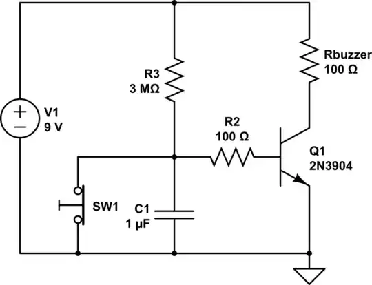
I am trying to design a circuit which switches on a buzzer when a switch (SW1) opens.

The image is not my circuit specifically.

enter image description here

The problem I am having is trying to figure out how to implement a delay before the NPN transistor turns the buzzer on. I want to try using an RC circuit but am not sure how to wire one up. I have tried to wire a capacitor up across the buzzer/potentiometer side of the circuit but that doesn't seem to cause any noticeable delay.

Any idead/tips on how I could better approach/solve this issue would be helpful.

JRE
  • 71,321
  • 10
  • 107
  • 188
Chunkey
  • 3
  • 1
  • I was looking to get the delay around 0.2 of a second – Chunkey Nov 28 '22 at 09:31
  • Then you may want to consider some kind of RTL AND gate. You have a switch tied to ground that can open up. Are you willing to consider using a double-pole variety? (Fewer parts that way.) Or stuck with single pole? – jonk Nov 28 '22 at 09:40
  • I wasn't very clear with the switch, that's part of a whole different circuit which basically acts like a switch. (The sensor) – Chunkey Nov 28 '22 at 09:45
  • Is it pre-grounded so that you cannot change the fact that it is tied to ground? Like an "NPN output" thing? – jonk Nov 28 '22 at 09:47
  • Are you talking about the fact that SW1 is directly connected to ground? It doesn't need to be connected straight to ground, that positioning was the only way I could see of turning the circuit on when it 'opens' – Chunkey Nov 28 '22 at 09:53
  • So, both ends of the switch are available for any use in any circuit? It's actually a real SPST switch driven by the sensor? (I'm not disputing, just asking to be sure.) – jonk Nov 28 '22 at 10:03
  • Yes, both ends can be used anywhere. the SPST is not driven by the sensor, it just represents how the sensor can function (ON/OFF) without having to add that to the circuit. All it does is just break/close the circuit. – Chunkey Nov 28 '22 at 10:06
  • The reason for all this is that you can consider using an RTL AND gate (one BJT.) One input to the AND gate is the switch condition without delay. The other input to the AND gate is the switch condition with an RC delay as you suggested using. Once both are on, the AND gate is finally on. So you use that final AND gate output to drive a BJT to turn the relay on. It the switch goes off the AND gate will immediately go off as well. That is the behavioral description. The actual analog circuit design will be a little more nuanced. But hopefully that gets the idea across. – jonk Nov 28 '22 at 10:08
  • I think i understand what you're talking about. Something like this? https://imgur.com/a/iCdIhLH . The main problem I had with the RC delay stuff was that I don't know how to do delay before turning on, having the alarm stay on for a duration I know how to do. – Chunkey Nov 28 '22 at 10:24
  • That's one of those *terrible* AND gates you see in textbooks (and should NOT see and if you see should immediately forget.) I mean a crafted RTL gate design like this. – jonk Nov 28 '22 at 10:26
  • I'm thinking three BJTs are needed, though. I'm going to bed now. May look at this later. – jonk Nov 28 '22 at 11:07

1 Answers1

0

Is this what you are trying to do?

With the switch closed the cap remains discharged and the transistor is off. When the switch is pressed (and therefore opens) it allows the cap to charge up and after about 0.2 seconds it will turn on.

The values of the cap and resistor will depend on the transistor you use and the supply voltage.

schematic

simulate this circuit – Schematic created using CircuitLab

ErikR
  • 4,987
  • 12
  • 18
  • Is the charge-up time just R*C? – Chunkey Dec 01 '22 at 05:52
  • It's related to RC and the proportionality constant will depend on the exact transistor you select because each transistor is slightly different. And it will also depend on the supply voltage because one RC time period is roughly 63% of the supply voltage. – ErikR Dec 01 '22 at 09:35