simulate this circuit – Schematic created using CircuitLab
Like many other DIYers with a one-off need to build a few li-ion battery packs and can't justify buying a spot welder, I am planning to build one myself. I did much reading and dug through my junk pile, and are leaning towards this setup built using what I have on hand. The TLDR question is: Will this work?
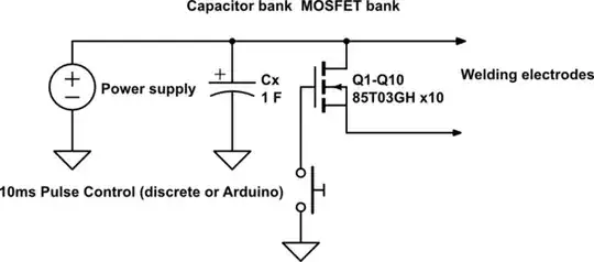
- A power supply, connected to...
- A bank of electrolytic capacitors, connected to...
- A parallel gang of (I think I now need 10) MOSFETs salvaged from two dead main boards. I could salvage up to 16 70T03GH (60A continuous) or 14 85T03GH (75A), with the gates connected to...
- A discrete/555 circuit or an Arduino to produce a consistently timed 10ms pulse to control the switching MOSFETs above. All this finally fires through...
- A pair of copper electrodes.
I have on hand:
- An old AT power supply, 8A@12v + 24A@5v
- Rehoused iMac G4 power supply, 10.83A@12v
- 20A@12v power supply off the 3D printer
- A "1000A" booster pack anchored by a 12v/20Ah SLA battery that I changed out a year ago.
- Two dead motherboards with 16 70T03GH and 14 85T03GH MOSFETs between them
- 555 and LM324 chips
- Arduino Micro
- Assorted discrete parts to build a circuit around 555/324/Arduino
- An assortment of capacitors from 1000 to 3300 uF, 8 of them rated above 12v.
- NMD-90 14/2 solid copper wires, easily made into electrodes.
- 4-gauge wires meant for car stereos
- Some copper pipes to cut electrodes out of, if needed.
My question is thus:
- Can it work?
- Is my stash enough for what I'm about to do, at least quantitatively?
- Can I do it with just a charged cap bank and no switch?
This question has been significantly revised before posting after I came across a youtube video of someone testing a spot welder at different power settings. He says (within the first minute, fortunately for me) that 90J over 10ms at 13v gives the best weld. Based on his other tests I believe 12v could also work. Now I have to design my build around the 90J figure. Some crude and (sometimes naive) calculations led me to 750A surge at 12v, and the cap bank would need to be 3.6F at 5v, well within supercap territory, and 12v supercaps are too expensive. He also said he used 1/0 welding wires to reduce loss. This is easier for me to get than supercaps from digikey.
Edit: I finally figured out how to add a schematic, so I added one representing my plan. Cx is the capacitor bank, 1F is just a placeholder value that it means to be a big bank.
