2

I have used several off-the-shelf mains voltage motion detectors over the last couple of months. Different makes and models. This kind of thing:

Picture of a generic motion detector

Often I have the issue that when they are off, they are not really off, i.e. the relay output still carries some voltage - less than in "on" state, but enough to light a LED in a connected circuit and false trigger an input. It's driving me crazy.

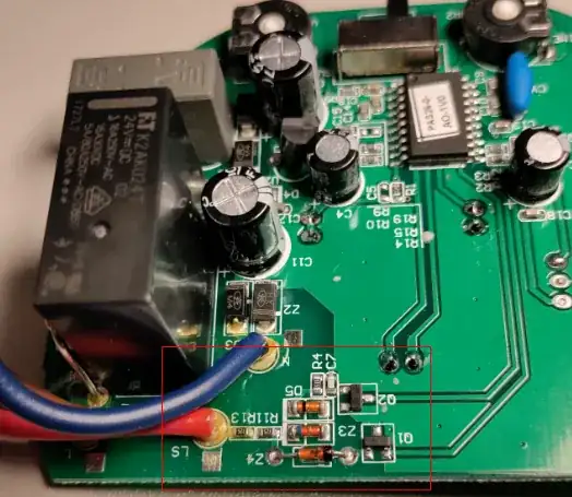
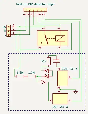
Today I have one like that again. The PCB is relatively simple, so I drew a schematic of what it is that is connected to the output.

Reverse engineered schematic

The upper SOT-23 device is marked "1E", the lower one "3E".

Photo of the circuit in question

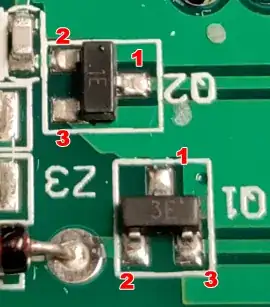
Pin numbers requested in comments:

Pin numbers

I will disconnect that part of the circuit as usual and it will probably work, but maybe someone can guess what the purpose of this circuit is?

AndreKR
  • 2,999
  • 3
  • 23
  • 30
  • What's the rest of the logic that it connects to? – user253751 Oct 26 '22 at 03:37
  • @user253751 The actual PIR detector... the main controller, the PIR sensor, the power supply, some caps, timer adjustment pot, etc. It's different in each detector. The two parts of the circuit are actually laid out a bit apart from each other, I'll add a photo. – AndreKR Oct 26 '22 at 03:47
  • @user253751 Done. – AndreKR Oct 26 '22 at 03:51
  • 1
    @AndreKR Just a clarification, if I may. Are you saying that the LS wire is providing you with some level of L (mains line level) sufficient to light up an LED when referenced to N? Is that what you are saying? Or something different? – jonk Oct 26 '22 at 05:19
  • @jonk When it's supposed to be off, yes, that's what I'm saying. And it's not just this particular model, I had three or four motion detectors that acted like this. – AndreKR Oct 26 '22 at 05:43
  • 1
    @AndreKR The N goes "off-screen" with respect to your schematic. So we cannot tell what's out there. True? – jonk Oct 26 '22 at 05:45
  • @jonk What do you mean? The cable goes to a screw terminal which then connects to mains. – AndreKR Oct 26 '22 at 05:48
  • How are you numbering the SOT23s? Can you add a zoomed in photo of one of the SOT23s with pin numbers added? – user57037 Oct 26 '22 at 06:12
  • 1
    @mkeith The schematic is drawn after the physical layout on the PCB, but I have added a pin number photo as well. – AndreKR Oct 26 '22 at 06:20
  • What type of circuit are you placing on the LS line when you detect the unwanted voltage? Have you measured the LS output with a load (to N) such as a small incandescent bulb? – Nedd Oct 26 '22 at 06:40
  • Possibly an MOV or RC snubber across the contacts. – Nedd Oct 26 '22 at 06:54

1 Answers1

1

The extra circuit that you outline would not provide enough current to light an LED on the LS wire. Is it possible there are other components on the LS wire such as a high voltage rated capacitor?
(Is there a component hiding to the left of the relay, or is the capacitor above the relay attached to the wires you show?)

I would guess that the extra circuit is trying to detect if the load switched wire (LS) is driving an old style incandescent bulb or a specialty bulb such as a florescent or pulsed LED bulb. A pulsed LED or florescent bulb may be flashing at a high rate (unseen by human eyes but seen by the electronic sensor). So the feedback to the controller would tell it to disregard any high frequency flashing.

Nedd
  • 10,391
  • 17
  • 24
  • Yes, the LED was in a circuit. That's a good hypothesis. I had the same problem with RF/microwave/radar motion detectors, but I guess the principle is the same - detecting high frequency changes in the power draw to filter them out? – AndreKR Oct 26 '22 at 05:57
  • If the relay has one or more other components across the contacts they might be for arc protection (usually for inductive loads). These might cause a small leakage current in the off state. Do note that if you do make modification to the device any UL/CSA/CE, etc, safety statements are voided. With that said, you might try removing any additional components directly across the contacts to prevent any leakage, (but then do not switch any inductive loads). – Nedd Oct 26 '22 at 07:16
  • If you are just trying to use the switched output as a signal, (and you don't want to modify the sensor board), you might try placing a load on the switched outputs, for example a tiny line voltage step down transformer, then detect the on state by the secondary voltage of the transformer. You may be able to add just a resistor shunt across the outputs to reduce the effects of the leakage. Just be sure that the resistor is of the appropriate wattage. – Nedd Oct 26 '22 at 12:08