0

Astable multivibrator coupled with complementary astable multivibrator:

astable multivibrator coupled with complementary astable multivibrator

I tried to build this schematic on a breadboard, but the complementary astable multivibrator circuit on the right does not work properly. The left astable one works fine for me.

Is there any advice to improve its reliability and reproducibility by adding something or replacing something?
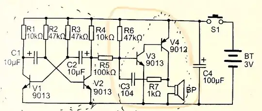
JRE
  • 71,321
  • 10
  • 107
  • 188
ankyxia06
  • 71
  • 4
  • A similar circuit has previously been asked about on here, with an analysis of why it's not a very good oscillator provided there. Does that help? – Hearth Sep 30 '22 at 04:45
  • yes, it explains a lot and it is helpful to understand this topic more deeply. However, I have to make it successful since I have many tests on hold with this circuit and I have to overcome this issue to move forward. changing a little bit on this circuit and achieving the same function can also be a way out. – ankyxia06 Sep 30 '22 at 06:09
  • thanks, originally i tried to post these schematics in one post, and yet failed. thanks for your effort and it's ok to wrap it up in other one. – ankyxia06 Sep 30 '22 at 06:15
  • Transistot current gains (Beta) and R6 value are crucial to operation. || When V4 turns iff C3 rhs is pulled to ground and C3 lhs is driven under ground. || "Playing with" R6 value can start/stop operation. – Russell McMahon Sep 30 '22 at 09:51
  • thanks McMahon, can you detail rhs and lhs? what are they short for. – ankyxia06 Oct 08 '22 at 09:49
  • also how does current gains affect. do you simply mean Emitter and connector on V4 connect or disconnect dependent on its base. if you have other implication please detail a little bit. – ankyxia06 Oct 08 '22 at 10:07

0 Answers0