1

I got CD40106B, CD4081B and TC4420.

It all works great but when I connect the output of the TC4420 to a power MOSFET or a BJT the TC4420 signal drops completely.

I've tried replacing the TC4420 with discrete push pull BJT and the same happens.

Here's the circuit:
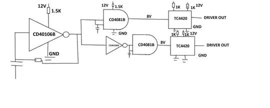
enter image description here

JRE
  • 71,321
  • 10
  • 107
  • 188
lidorov19
  • 71
  • 6
  • 6
    What are all the supply resistors doing? – Tim Williams Sep 19 '22 at 18:25
  • I am actually really struggling with those resistors @TimWilliams , I've read the PDFs of those CMOS Gates and MOSFET Driver and they say there is max current rating . For the CMOS Gates it's 10mA , and for the TC4420 it's 3mA (and in this case my resistors are too low but nothing bad happens and I don't get it) . I really think I don't understand the PDF , what are you suggesting – lidorov19 Sep 19 '22 at 18:30
  • 1
    As JRE said. You CAN add a small series resistor from driver output to gate to limit gate drive peak to a bit more than needed. MAyve 10 Ohms. The reason is that 1. excessively high drive may lead to very rapid turnon and sharper switching edges than desired and related somewhat 2. Series R reduces gate ringing. – Russell McMahon Sep 22 '22 at 01:55
  • @RussellMcMahon Thanks , I actually needed the series resistance to reduce the ringing , thank you - was really helpful . – lidorov19 Sep 22 '22 at 12:24
  • 1
    @lidorov19 If you still have gate ringing problems a good fix is a small Schottky diode connected reverse biased from gate to source. This does not conduct under gate drive but negative ringing voltage gets clipped by the schottky, rapidly removing ringing energy. – Russell McMahon Sep 22 '22 at 15:54
  • 1
    @lidorov19 ... || A final useful item if you are driving an inductiove load is a zener diode g-s connected. Vzener slightly higher than max drive voltage. This clamps tghe gate at Vzener max and stops Miller capacitance coupled transients from the drain driving the FET to destruction. Can be immensely effective when needed. Schottky or zener mount electrically close to g-s leads. – Russell McMahon Sep 22 '22 at 15:54
  • @RussellMcMahon WOW thank you so much , indeed "immensely effective" - it is a life changer for me now ! – lidorov19 Sep 22 '22 at 17:47

1 Answers1

8

You've misread the TC4420 datasheet, as well as the datasheets of the 40106 and the 4081.

enter image description here

\$I_S = 3mA\$ in the datasheet does not mean that you have to limit the supply current to 3mA. It means that the chip will draw 3mA when connected and working properly.

Remove the resistors between the power supplies and the supply pins and your problems should go away.

JRE
  • 71,321
  • 10
  • 107
  • 188