4

I started a project to embed a Raspberry Pi in an old radio. One of the challenges is that the radio has a hard power-off button, so I want the Pi to have power for another 10-30 s so it can shutdown itself. The Pi has a hat with a power converter so it's powered by 12 V rather than the normal 5 V. The 12 V comes from an external PSU, so I can bypass the switch, I don't need a capacitor to provide actual power.

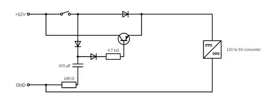
I gave it a try but I have admittedly not done any circuit design since I stopped playing with Fisher Technik, 35 years ago. So the below is an attempt.

Circuit Diagram

Questions:

  1. Will the above work, or did I oversee something?
  2. Can it be done in a simpler/better way?
  3. The values for resistors/capacitor are just randomly chosen. What would be reasonable values to achieve this 30 s delay?
TonyM
  • 22,898
  • 4
  • 39
  • 64
treuss
  • 143
  • 5
  • 1
    Have you simulated it? Does the Raspberry Pi plus the power converter add-on have a concept of soft power on or off button? – Justme Sep 12 '22 at 13:09
  • Simulation did not work in the tool I had used to draw this. Will need to search for a working simulator. The pi has GPIO pins, I will wire pressing the off-button to changing one of the pins which will trigger shutdown from software side. – treuss Sep 12 '22 at 13:13
  • It stands a chance of working but not as effectively as using a p channel MOSFET – Andy aka Sep 12 '22 at 13:26
  • Does the 12 V power source stay on after the radio is turned off? If not, you will need a much larger capacitor to power the pi for 30 s. AND - what is the current draw of the pi while shutting down? – AnalogKid Sep 12 '22 at 13:33

1 Answers1

3

I want the pi to have power for another 10-30s so it can shutdown itself

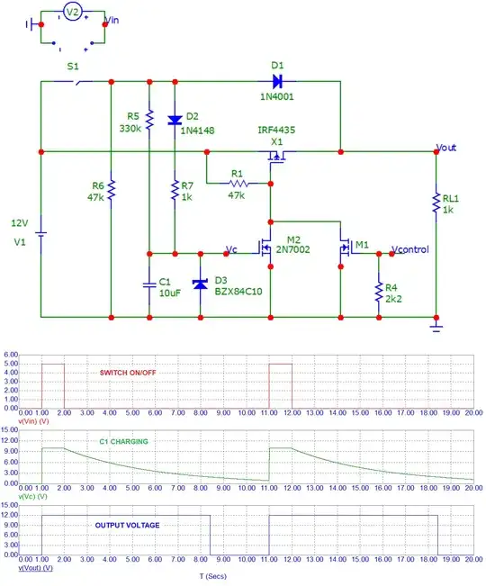
I've re-written this answer with a new design that I think now does what you want without incurring the diode drops in the supply lines: -

enter image description here

If left to its own devices without external control from the pi (via Vcontrol), the circuit shuts down after about 6.5 seconds. I've purposefully made this shorter than the 10 to 30 seconds specified in the question just to run the simulation. This time can be extended by increasing C1. A doubling of C1 should achieve about 13 seconds delay before power is fully removed from the load (RL1 in the diagram).

V2 and S1 mimic the power on/off button. In the simulation I have the power button activated for one second then off for 9 seconds (just for convenience). The p-channel MOSFET is a fairly random one chosen from the micro-cap suite and, of course, it should work with any suitable MOSFET.

If the incoming supply is more than 15 volts DC, take care to ensure that the p-channel MOSFET is gate protected. Some MOSFETs won't need this but, at supplies above 20 volts, most will. This can be fairly easily achieved with an added resistor in series with M1/M2's common drain connection to X1 and a Zener diode between X1's gate and source.

If the switch on pulse was reduced to 100 ms: -

enter image description here

There is still about 6.5 seconds of delay before MOSFET X1 turns off. If C1 was increased to 22 μF we see a longer delay-off time as expected (a tad over 14 seconds): -

enter image description here

Andy aka
  • 456,226
  • 28
  • 367
  • 807
  • Many Thanks! Do I understand correctly that upon boot, the pi should on boot provide power (via GPIO) to the M2 and upon shutdown, the GPIO pin will go down, so power is ceased. What I am a bit scared off is whether the GPIO pin won't go down already during shutdown, not only at the end of it. – treuss Sep 12 '22 at 14:55
  • Yes, good point. You will need a pull down resistor (maybe 2k2) on the gate to ensure that an open-circuit IO line (or high impedance IO line) properly keeps the gate low. Then when you want to shut-down, just set the pin for input and the 2k2 will do the rest. – Andy aka Sep 12 '22 at 15:55
  • 1
    @Andyaka When input power is removed, where does the Pi get the power to stay on for as long as it needs? – GodJihyo Sep 12 '22 at 16:56
  • @GodJihyo yes you are right, my schematic is lacking in important information as to where the on/off switch goes. I shall amend. – Andy aka Sep 12 '22 at 17:06
  • @Andyaka I tried simulating this, first thing I noticed is that there's an NMOS symbol for M1, no biggie, schematic typo. The main problem I ran into was that the output would be 8.5V (same as the Vgs of the model I used) when it was supposed to be off. I found that connecting R1 to M1's source instead of the switch fixed it, maybe you could review and update. Thanks. – GodJihyo Sep 12 '22 at 20:48
  • @GodJihyo that is a PMOS symbol for M1 as per this: https://www.allaboutcircuits.com/technical-articles/schematic-symbols-for-electronic-components-transistors/ – Andy aka Sep 12 '22 at 22:40
  • Ah, not used to seeing that one. Not confusing at all having two symbols for the same thing with arrows pointing in opposite directions :| – GodJihyo Sep 13 '22 at 02:07
  • I've changed the circuit to something more suitable @GodJihyo I believe. – Andy aka Sep 13 '22 at 11:13