2

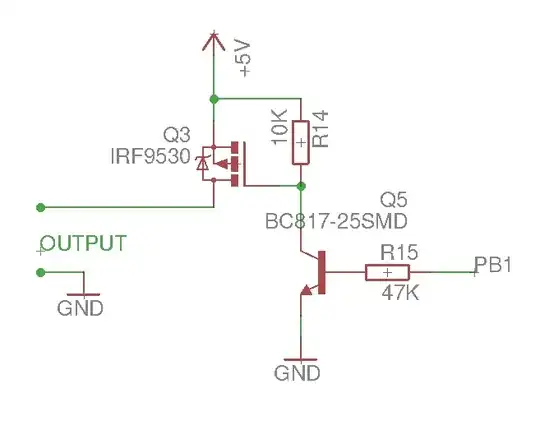
I have the following circuit attached to my ATTiny13A. More specifically, attached to its PB1:

enter image description here

I'm doing this to initialize the port:

//init
DDRB |= (1<<DDB1); PORTB &= ~(1<<PB1);

//turn ON PORTB |= (1<<PB1);

//turn OFF PORTB &= ~(1<<PB1);

There is a 1 s CTC defined, which turns ON PB1 at startup + 6 s, and turns it off at startup + 10 s.

This works perfectly, until I attach some load to the OUTPUT (100 mA @ 5 V).

If I attach my load, it causes the AVR to either

  • immediately reset after turning ON PB1
  • hang after turning ON PB1, then reset by the WDT

Note 1: Q3 is a DMP3056LSD.

Note 2: The 5 V is provided by my computer via USB, and I also tried with a powerbank's USB. The 5 V was also checked with an oscilloscope, and it's rock solid, i.e. the voltage is not dropping below AVR's resetting voltage.
ocrdu
  • 9,195
  • 22
  • 32
  • 42
Daniel
  • 949
  • 10
  • 22
  • Put a snubber on the output. – Tim Williams Aug 29 '22 at 13:33
  • 2
    You might be about to learn about the importance of local decoupling capacitors. (I'm not sure though since you don't seem to be able to detect any glitching on the scope!) Try adding 47 - 100 uF in parallel with 100 nF across the supply pins of your circuit. [Edit] your question to include details on your load. – Transistor Aug 29 '22 at 13:35
  • 3
    You have amended your question in such a way that it made my answer inappropriate in places. For this reason alone I have rolled back your question to how it stood originally. Whenever an answer is provided, great care should be taken when amending a question to make sure you don't invalidate that answer. If you want to add an update section below the original question that's fine but, don't tamper with stuff in the original text of the question. – Andy aka Aug 29 '22 at 14:05
  • Is the load a relay coil, per chance? – Lundin Aug 29 '22 at 14:17
  • @Andyaka: sorry, I haven't seen your answer yet at that time I changed the question. – Daniel Aug 29 '22 at 14:18
  • @Lundin: No, it's actually a "simple" USB power meter by ChargerLAB, KT-002. – Daniel Aug 29 '22 at 14:18
  • @Daniel you posted your edited question 12 minutes after I had left my answer. – Andy aka Aug 29 '22 at 14:20
  • @Andyaka: yes, my browser lost connection, and didn't show the update before I tried posting and realized the connection problem. Afterwards, I had to restart my network, and posting was done, and then I could see your answer :) – Daniel Aug 29 '22 at 14:23
  • 1
    "it's actually a "simple" USB power meter by ChargerLAB, KT-002." - please post a schematic and/or photo of the power meter, ATTiny and their power supplies, showing all wiring. – Bruce Abbott Aug 29 '22 at 14:27
  • For no problem "testing" on the PC USB port, always use an "isolated" USB transceiver ... unless you don't care about your USB port on the PC ... – Antonio51 Aug 29 '22 at 16:51
  • Do you have an oscilloscope available? – user253751 Aug 29 '22 at 17:02

1 Answers1

7

Take your pick: -

  1. Your 5 volt supply cannot sustain a 100 mA load.
  2. The 100 mA load current is flowing back into GND/0 volts and, due to bad wiring of the 0 volts, it's glitching the MCU and resetting it.
  3. The 100 mA load may take 100 mA under steady-state conditions but, it has a high inrush current when activated.
  4. Your 100 mA load is in fact taking a lot more current than 100 mA.
  5. You have a connection/wiring error.
  6. You need more supply de-couplers on your MCU
  7. Your load is inductive and you need a fly-back diode to prevent back-emfs upsetting your circuit.
Andy aka
  • 456,226
  • 28
  • 367
  • 807
  • 3
  • Power is coming from a Powerbank, which I believed is "well-decoupled". However it wasn't, and providing a 100uF onto the +5V eliminated all problems.
  • – Daniel Aug 29 '22 at 15:56