I am converting the voltage on a kiln from AC to DC. The kiln (48 A, 240 V) holds two crucibles for melting colored glass. When I gather glass using a steel pipe for glassblowing, I receive a strong shock if I am simultaneously grounded.
I theorize that the AC current is causing changes in the glass chemistry. Glass formulas which should be deeply purple (MnO2 addition) are pale and a silver opal glass acts reduced without addition of otherwise essential reducing agents.
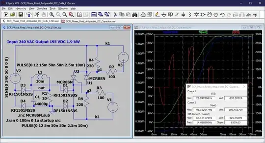
I have installed a full-wave bridge rectifier and even tried to add a pair of capacitors (200 V, 20000 μF) running in parallel. This promptly blew my superconductive fuses above the SCR due to a surge current to charge the capacitors. At this point, the schematic below was submitted by member @PSTechPaul to help me realize this idea:
His answer is to run my capacitors in series (400 V, 10000 μF) and add a custom built 2 mH induction coil (choke) made from a microwave oven transformer, or MOT, to filter the flow of ripple current.
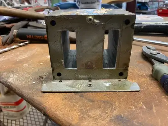
I have stripped down a microwave oven transformer to a bare laminated iron core. I plan on winding the coil with 10 AWG insulated, stranded wire.
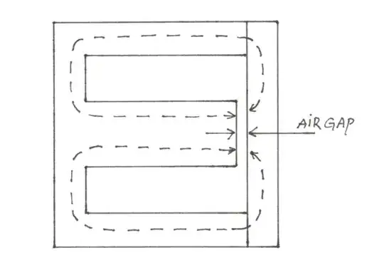
The part needs an air gap as well and I'm not sure how to construct one. Lots of YouTube videos exist to build custom transformer power supplies from MOTs, but I can't find one for building a choke. I have an LCR meter on order and a small oscilloscope/signal generator as well. I think I know how to test for inductance but any tips would be greatly appreciated. Is this a proper location for an air gap (see below) or could it be slotted anywhere through the laminated iron?
I'll be limited on the ability to size the gap to a saw blade's width so hoping that works. This website looks like a great resource for this project, but I wonder if I'll be better off determining the specs on my coil as I wind it?
This question is the result of advice I received in this post: 240V (North America) bridge rectifier with parallel filter capacitors is blowing fuses above the bridge


