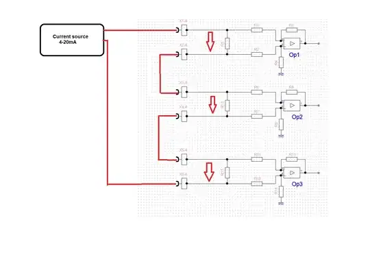
I am taking the output of the shown differential amplifier to the microcontroller (1, 2 and 3).
Each opamp here is in a different PCB but all are being fed by the same supply (same ground) and the same current source as in the image.
A colleague has advised being cautious about the common mode issue in this design.
I am not able to understand what is the common mode issue from textbooks, tutorials, etc.
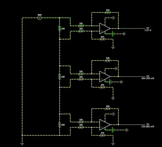
Simulation of the circuit shows different outputs for the same current which is confusing but is still not helpful in understanding.
Would anyone please help explain this issue?

